
Roller shutter anti-theft locket with two-way linkage locking mechanism

A locking mechanism and rolling shutter technology, applied in the field of rolling shutter locks, can solve the problems of secondary injury, locking head, single force point, etc. , the effect of simple process structure

Pending Publication Date: 2019-08-27
鲁海文
View PDF0 Cites 0 Cited by
  • Summary
  • Abstract
  • Description
  • Claims
  • Application Information

AI Technical Summary

Problems solved by technology

There are mainly five disadvantages: First, the gear transmission structure device used to control the stroke or displacement is prone to position deviation due to the vibration of the door body, and the phenomenon of stuck lock head and teeth may easily cause mechanical failure
Second, the rolling shutter doors and windows are displaced by the track, and the bolt anti-theft can only be used as an auxiliary security function. It is easy to pry up the door body when the track is vertically pried, so the bolt on the rolling shutter door and window does not realize the real anti-theft effect
Third, the point of stress is single. In the face of natural disasters, especially when typhoons hit coastal areas, the shutters and windows are often in a mess, causing secondary damage to personnel and property.
Fourth, the existing rolling gates require a key to open and close, and there is no emergency opening method when an emergency occurs inside the gate
Fifth, limited by the existing gear structure device, it seriously hinders the development trend and innovation foundation of automation and intelligent application in the rolling door and window industry. Therefore, we propose a rolling door and window anti-theft lock with a two-way linkage locking mechanism to solve the problem. Problems occurring in the above-mentioned background technology

Method used

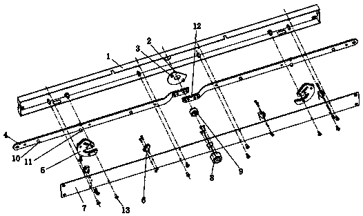
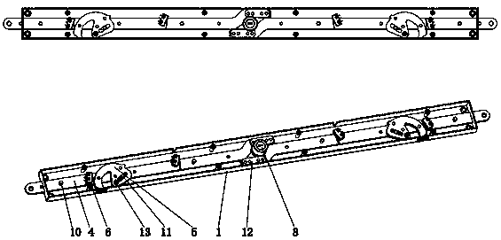
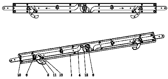

Image

  • Roller shutter anti-theft locket with two-way linkage locking mechanism
  • Roller shutter anti-theft locket with two-way linkage locking mechanism
  • Roller shutter anti-theft locket with two-way linkage locking mechanism

Examples


Embodiment Construction

[0015] The following will clearly and completely describe the technical solutions in the embodiments of the present invention with reference to the accompanying drawings in the embodiments of the present invention. Obviously, the described embodiments are only some of the embodiments of the present invention, not all of them. Based on the embodiments of the present invention, all other embodiments obtained by persons of ordinary skill in the art without making creative efforts belong to the protection scope of the present invention.

[0016] see Figure 1-3 An anti-theft lockset for rolling doors and windows with a two-way linkage locking mechanism, including a lock case 1, a dial wheel 2, a crank stroke driving nail 3, a pull rod 4, a lock hook 5, a micro switch 6, a bottom plate 7, a lock head 8, a dial shaft 9, Crank travel positioning nail 10 and transmission guide nail 11, the number of pull rods 4 is two, pull rod 4 is arranged inside the lock housing 1, the two pull rod...


PUM


Abstract

The invention discloses a roller shutter anti-theft locket with a two-way linkage locking mechanism. The roller shutter anti-theft locket comprises a lock case, a thumb wheel, a curved block stroke drive nail, pull rods, latch hooks, microswitches, a base plate, a locking head, a thumb wheel axle, curved block stroke positioning nails and drive guiding nails. The lock case, the thumb wheel, the curved block stroke drive nail, the pull rods, the latch hooks, the microswitches, the base plate, the locking head, the thumb wheel axle, the curved block stroke positioning nails, the drive guiding nails, curved block stroke guide slots and a curved block are mutually matched. The mechanism has the advantages of simple process structure and reliable mechanical performance; by installing a shutterlock with the device, security drawbacks and potential hazards brought by a traditional roller shutter lock can be thoroughly overcome; during installation, the roller shutter lock can be randomly selected among multiple hooks, dual hooks and single hook for installation by simple and convenient operation; a two-way opening and locking signal source is arranged to provide automatic and intelligentapplication and innovative base for the roller shutter, so that the roller shutter better meets the demands of people on beautiful life.

Description

technical field [0001] The invention relates to the technical field of rolling shutter locks, in particular to an anti-theft lockset for rolling shutter doors and windows with a two-way linkage locking mechanism. Background technique [0002] Traditional mechanical roller shutter locks generally use the lock cylinder drive gear transmission structure to realize the lateral auxiliary anti-theft effect of the bolt in place. There are mainly five disadvantages: first, the gear transmission structure device used to control the stroke or displacement is prone to position deviation due to the vibration of the door body, and the lock head and teeth will be stuck, which will easily cause mechanical failure. Second, the rolling shutter doors and windows are displaced by the track, and the bolt anti-theft can only be used as an auxiliary security function. It is easy to pry up the door body when the track is vertically pried, so the bolts on the rolling shutter doors and windows have ...

Claims


Application Information

Patent Timeline
Patent Type & Authority Applications(China)
IPC IPC(8): E06B9/86E05B65/00
CPCE05B65/0021E06B9/86E06B2009/801
Inventor 鲁海文
Owner 鲁海文
Learn More