
Vehicle running lane positioning method and device as well as terminal

A vehicle driving and positioning method technology, applied in the field of map navigation, can solve the problems of difficulty in mass production, high-precision maps and lidars are expensive, and achieve the effects of high reliability, ease of mass production and use, and reduced manufacturing costs.

Pending Publication Date: 2019-08-27
福瑞泰克智能系统有限公司
View PDF9 Cites 20 Cited by
  • Summary
  • Abstract
  • Description
  • Claims
  • Application Information

AI Technical Summary

Problems solved by technology

[0005] The technical problem to be solved by the present invention is that high-precision maps and laser radars are expensive and difficult to mass-produce

Method used


Image

  • Vehicle running lane positioning method and device as well as terminal
  • Vehicle running lane positioning method and device as well as terminal
  • Vehicle running lane positioning method and device as well as terminal

Examples


Embodiment 1

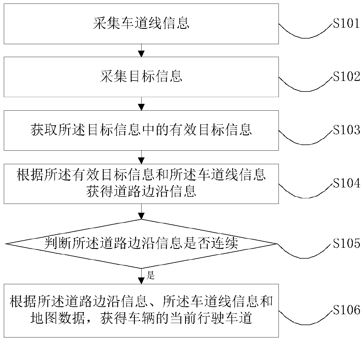
[0094] An embodiment of the present invention provides a vehicle lane positioning method, such as figure 1 As shown, the method includes:

[0095] S101. Collect lane line information;

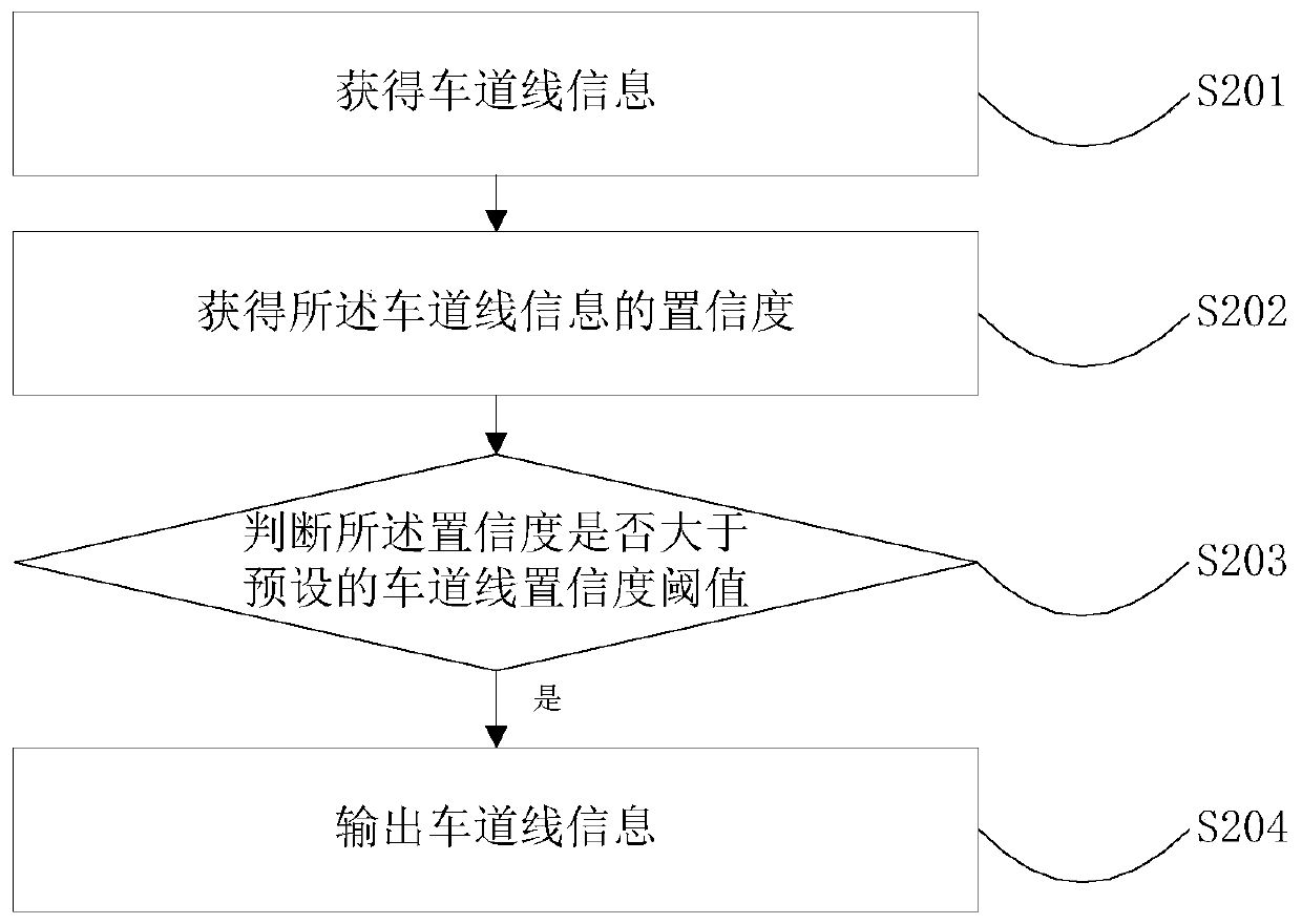
[0096] Further, the collection of lane line information includes:

[0097] S201. Obtain lane line information;

[0098] S202. Obtain the confidence level of the lane line information;

[0099] S203. Judging whether the confidence degree is greater than a preset lane line confidence threshold;

[0100] S204. If yes, output lane marking information.

[0101] Further, before collecting the lane line information, it is judged whether the lane line information can be collected, and if the lane line information cannot be collected, the vehicle lane positioning method cannot be used.

[0102] Specifically, the prerequisite for realizing lane-level positioning in the method is that lane line information can be collected normally. When the lane line information cannot be collected, that is, when t...

Embodiment 2

[0157] A feasible embodiment of the present invention provides a positioning device for a vehicle driving lane. The device includes: a lane line collection module 1301, a target information collection module 1302, a valid target information acquisition module 1303, a road edge information acquisition module 1304, a road edge continuity judgment module 1305, and a lane information acquisition module 1306;

[0158] The lane line collection module 1301 is used to collect lane line information;

[0159] The target information collection module 1302 is used to collect target information;

[0160] The valid target information obtaining module 1303 is used to obtain valid target information from the target information;

[0161] The road edge information obtaining module 1304 is used to obtain road edge information according to the lane line information and the effective target information;

[0162] The road edge continuity judging module 1305 is used to judge whether the road edge ...

Embodiment 3

[0178] An embodiment of the present invention provides a terminal, the terminal includes the above-mentioned device for positioning a driving lane of a vehicle, and the terminal may be a vehicle.


PUM


Abstract

The invention relates to map navigation, and provides a vehicle running lane positioning method and device as well as a terminal. The method comprises the following steps: acquiring lane line information; acquiring target information; acquiring effective target information in the target information; acquiring roadside information according to the effective target information and the lane line information; judging whether the roadside information is continuous or not; and if so, acquiring lane map information of a current vehicle running lane according to the roadside information, the lane lineinformation and map data. The roadside information is acquired through linear fitting or curved fitting, or by finding an offset boundary. Through adoption of the method, the vehicle lane can be determined on a low-accuracy navigation map under to the assistance of a visual sensor and a radar sensor; the accuracy of a lane-level map is achieved; the vehicle manufacturing cost is lowered; and convenience is brought to the volume production of vehicles.

Description

technical field [0001] The invention relates to the field of map navigation, in particular to a positioning method, device and terminal for vehicle driving lanes. Background technique [0002] With the continuous development of Advanced Driving Assistant System (ADAS), more automated and more difficult functions such as HWA (Highway Assist) and HWP (Highway Pilot) have gradually come into people's sight, whether it is HWA or HWP, the premise of its realization is automatic lane change, and the premise of automatic lane change is that the vehicle must be able to achieve lateral lane-level positioning. [0003] In the existing vehicle lane-level positioning methods: manufacturers of high-precision maps such as NavInfo and L4-oriented manufacturers such as Google, realize lane-level positioning directly through GPS signals input to high-precision maps with centimeter-level accuracy. It is implemented in the precision map and cooperates with Lidar to realize lane-level position...

Claims


Application Information

Patent Timeline
IPC IPC(8): G01C21/30
CPCG01C21/30
Inventor 陈永春朱科引曹润滋邹欣张英翰李宝峰吴鹏
Owner 福瑞泰克智能系统有限公司
Learn More