Bulk grain metering weighing system

A weighing system and measuring scale technology, which is applied in the field of weighing instruments, can solve the problems of high cost of manpower loading and unloading, low efficiency, and rising grain storage costs, so as to reduce the possibility of human error, reduce labor costs, and improve The effect of weighing efficiency

Inactive Publication Date: 2019-08-27
JINAN JINZHONG ELECTRONICS SCALE
10 Cites 4 Cited by

AI-Extracted Technical Summary

Problems solved by technology

The measurement accuracy of truck scales is low. For expensive materials such as grain, the error is relatively large; manpower loading and unloading trucks are costly and time-consuming, and they need to be loaded and unload...

Abstract

The invention discloses a bulk grain metering weighing system. The system comprises an input belt conveyor, a weighing system, a computer server, an output belt conveyor and a video monitoring device;the input belt conveyor conveys the grain to a weighing system, the weighing system is wirelessly connected with the computer server and transmits the weighing data to the computer server; the weighing system outputs the weighed grain through the output belt conveyor; and the video monitoring device is arranged on the weighing system. The combination of the discontinuous accumulative weighing metering and grain conveying of the grain warehouse-inputting and outputting is realized, the grain warehouse input-output transporting, warehouse changing and weighing problems are solved, the quantitative warehouse inputting-outputting, quantitative loading, automatic metering and like functions are realized, and then the data is uploaded to the computer server, the classification group querying and management can be performed on the data, and the management efficiency is improved.

Application Domain

Technology Topic

Image

  • Bulk grain metering weighing system
  • Bulk grain metering weighing system
  • Bulk grain metering weighing system

Examples

  • Experimental program(1)

Example Embodiment

[0023] The features and principles of the present invention will be described in detail below with reference to the accompanying drawings. The examples cited are only used to explain the present invention and are not intended to limit the protection scope of the present invention.
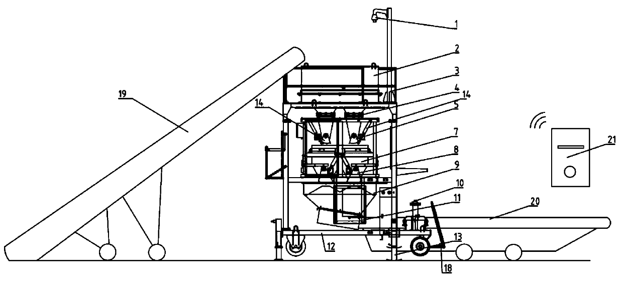
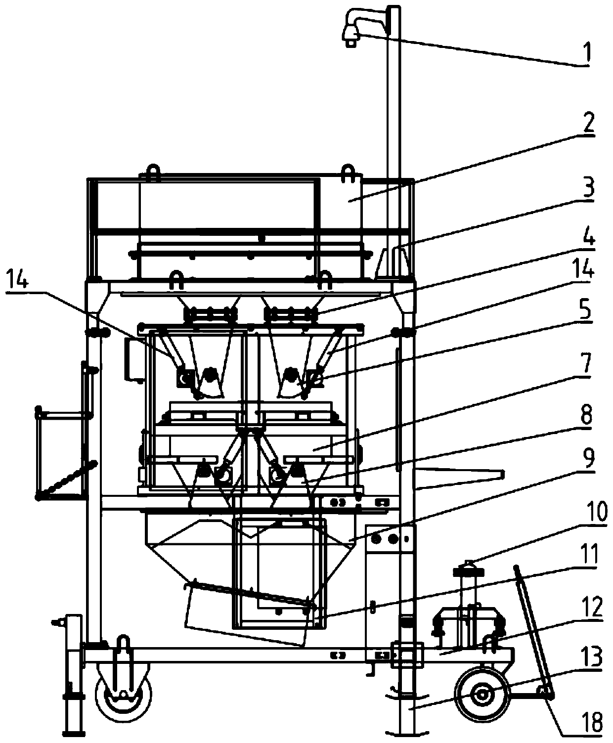
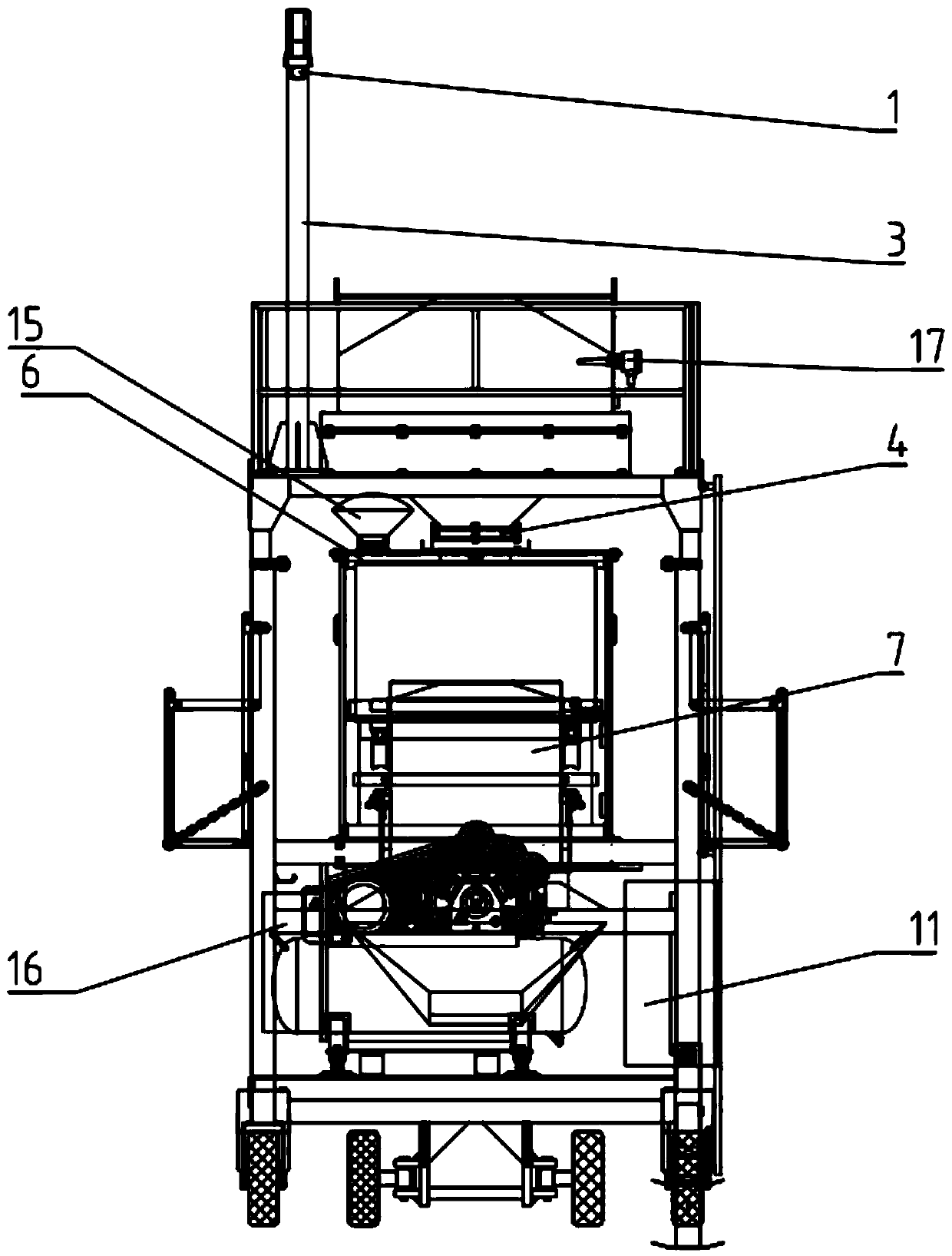
[0024] Such as Figure 1 to Figure 4 As shown, this kind of bulk grain weighing system includes an inlet belt conveyor 19, a weighing system, a computer server 21, an outlet belt conveyor 20 and a video monitoring device. The inlet belt conveyor 19 transports the grain to the weighing system, The weighing system is wirelessly connected to the computer server 21 and transmits weighing data (including weight, bucket number, warehouse number, vehicle number, weighing time, etc.) to the computer server 21. The computer server summarizes the data and generates reports. The weighing system outputs the weighed grain through the outlet belt conveyor 20, and the video monitoring device is installed on the weighing system.
[0025] The weighing system includes a frame, which is mounted on a mobile trolley 12, and the bottom of the mobile trolley 12 is provided with lifting legs 13. A tow bar is arranged in front of the mobile trolley 12, and there is an inclined limit block 18 between the tow bar and the mobile trolley 12. The mobile trolley 12 is pulled to move by pulling the traction rod. When the traction rod is not used, the traction rod is placed on the limit block 18 to limit the angle of the traction rod from being too large and prevent the traction rod from hitting the air compressor 10. The steering system of the mobile trolley 12 uses a linkage system to ensure the synchronization of the two front wheels. In order to reduce the steering resistance, the wear pad is designed with a lubricating oil structure. A damping spring shock absorber is added under the air compressor fixed on the mobile trolley to avoid the influence of vibration and weight when the air compressor is running. The lifting leg 13 plays a supporting role during work. When changing the site, the leg can be retracted by shaking the handle to prevent it from hitting obstacles.
[0026] A power control cabinet 11 is also installed on the mobile trolley to provide power for all power components in the system.
[0027] An upper buffer hopper 2 is installed on the frame, and the upper buffer hopper 2 is connected to a feeding device 5 through a soft connection 4. The soft connection 4 is a flange connection type by folding a large main filter cloth and sewing four small filter cloths. The soft connection is an open way, one of which is overlapped and connected by a hook and loop fastener.
[0028] The feeding device 5 is installed on the frame through a weighing bracket 6, and an air balancing device 15 is installed on the weighing bracket 6. The air balancing device 15 includes a filter cover and a clamp, and the filter cover is connected to the feeding device 5 through the clamp. When the upper buffer hopper feeds the feeding device 5, the filter cover opens due to the increase in the pressure in the feeding device; when the feeding device 5 discharges, the filter cover retracts due to the decrease in the pressure in the feeding device. The filter cover is sewn with a filter cloth with good air permeability. The filter cover can expand or contract with the increase or decrease of the air pressure in the feeding device, balance the internal and external air pressure, and reduce the influence of the air pressure on the weight.
[0029] Below the feeding device 5 is a weighing device 7. Both the feeding device 5 and the weighing device 7 are provided with two discharge doors 8 at the bottom. The double discharge door structure is designed to simultaneously feed and discharge simultaneously, which improves The feeding and unloading speed is improved. By increasing the length of the scale body, the overall height of the equipment is reduced, and the connection with the user equipment is ensured.
[0030] The discharge door 8 is fan-shaped, and the discharge door 8 is connected with the air cylinder 14 and is driven by the air cylinder 14 to complete the door opening/closing action. An air compressor 10 is installed on one side of the frame. The air compressor 10 is connected to a smart weighing terminal 16 through a pipeline. The smart weighing terminal 16 is connected to the cylinder 14 and controls the action of the cylinder 14. The cylinder on the weighing device 7 adopts a symmetrical arrangement and shares a base to reduce the vibration of the weighing bucket when the material door is opened and closed.
[0031] The intelligent weighing terminal 16 has a preheating function. When starting, the solenoid valve can be controlled to make multiple on and off within the time set by the program, and the cylinder can perform multiple telescopic actions to overcome the defects of the solenoid valve and the cylinder when the lubricating grease is thick and the sealing ring is too tight. Quickly enter the normal working state.
[0032] Below the weighing device 7 is a lower buffer hopper 9, which temporarily stores materials and transports the materials away through a conveyor belt below it.
[0033] A transparent glass observation window is installed on the weighing bracket 6, which is realized by pressing the acrylic glass with a pressing plate, and the state of the internal cylinder can be seen without opening the door of the weighing bracket, which is convenient for maintenance.
[0034] A camera 1 is installed on the top of the frame through a camera column 3, and the camera 1 is a camera that can rotate in a three-dimensional direction. The camera column 3 is installed in the fixed hole of the frame and can be rotated at any angle around the center of the fixed hole.
[0035] A level gauge 17 is installed in the upper buffer hopper 2, and the level gauge 17 is electrically connected to the intelligent weighing terminal 16.
[0036] The weighing process is:
[0037] The upper-level feeding equipment transports the material to the upper buffer hopper 2. When the system enters the automatic operation state, the intelligent weighing terminal 16 sends a control signal to open the feeding door in the feeding device 5 and start feeding. When the weight of the material reaches the set value , Close the feeding door, stop feeding, the intelligent weighing terminal 16 records the weight of the material in the weighing hopper in the weighing device 7 (gross weight record), and then the intelligent weighing terminal 16 sends out a control signal, the weighing device 7 The discharge door is opened, and the material is discharged from the weighing hopper to the lower buffer hopper 9. After the weighing hopper is finished unloading, the discharge door is closed, and the intelligent weighing terminal 16 records the weight of the remaining material in the weighing hopper (tare record). According to the gross weight record and the tare weight record, the intelligent weighing terminal 16 automatically calculates the net weight of the material and starts the next weighing. After each weighing, the net weight of the material is added to the cumulative net weight. When the accumulated net weight reaches the preset batch weight, the weighing process automatically stops. The level gauge 17 is installed in the middle of the upper buffer hopper 2. When the upper-level feeding equipment conveys materials too fast, the material in the hopper gradually increases to the level gauge 17, and the intelligent weighing terminal 16 sends a control signal to stop the first level of feeding. During the operation of the material equipment, the intermediate equipment continues to operate, and the discontinuous accumulating scale works normally. Although the material in the upper buffer hopper 2 will continue to increase for a certain period of time, due to the continuous discharging of the discontinuous accumulative scale, the materials carried by the intermediate equipment are limited, and the increase in materials is limited, and the upper buffer hopper 2 will not eventually overflow. When the material is lower than the level gauge 17, the intelligent weighing terminal 16 sends a control signal to start the first-level feeding equipment. Camera 1 can remotely monitor on-site conditions.
[0038] It also includes an electrical control device, including a control input device and a control output device, the control input device is connected to the weighing device, the control output device is connected to the inlet belt conveyor and the outlet belt conveyor; the control output device includes a control cabinet, The control cabinet is equipped with n sets of industrial sockets, and is equipped with a PLC programmable controller, RS485 module, display screen, status indicator, and electrical conversion switch; the PLC programmable controller is electrically connected to n sets of industrial sockets, The input port of the industrial socket is electrically connected to the inlet belt conveyor and the outlet belt conveyor; the PLC programmable controller is electrically connected to the upper control port through the RS485 module; the output port of the PLC programmable controller is electrically connected An industrial socket is connected, and the input port of the industrial socket is electrically connected to the inlet belt conveyor and the outlet belt conveyor.
[0039] The working process of a bulk grain measuring system includes the following steps:
[0040] Step 1.1, the administrator makes a card on the computer server, and writes the preset weighing weight, warehouse number and other information into the card.
[0041] Step 1.2, the operator takes the card to the smart weighing terminal to swipe the card to start the bulk grain measurement system.
[0042] Step 1.3, the intelligent weighing terminal sends instructions to the electrical control device to start the inlet belt conveyor and the outlet belt conveyor, and send the grain to the discontinuous cumulative weighing device.
[0043] Step 1.4, the intelligent weighing terminal controls the discontinuous cumulative weighing device to weigh, and transmits the result to the computer server.
[0044] Step 1.5, after the weighing is completed, unload the grain into the outlet belt conveyor.
[0045] Step 1.6, the export belt conveyor will send the grain into the warehouse or load the truck.
[0046] The above-mentioned embodiments are only descriptions of the preferred embodiments of the present invention, and are not intended to limit the scope of the present invention. Without departing from the design spirit of the present invention, those skilled in the art shall apply various modifications and improvements to the present invention. Expanded into the scope of protection determined by the claims of the present invention.

PUM

no PUM

Description & Claims & Application Information

We can also present the details of the Description, Claims and Application information to help users get a comprehensive understanding of the technical details of the patent, such as background art, summary of invention, brief description of drawings, description of embodiments, and other original content. On the other hand, users can also determine the specific scope of protection of the technology through the list of claims; as well as understand the changes in the life cycle of the technology with the presentation of the patent timeline. Login to view more.

Similar technology patents

Alternating current-direct current micro-grid system on basis of electricity energy collector

InactiveCN104578166ASimple structure and control processImprove management efficiencySingle network parallel feeding arrangementsSingle ac network with different frequenciesPower gridGrid connection
Owner:STATE GRID CORP OF CHINA +1

Classification and recommendation of technical efficacy words

  • Improve management efficiency
  • Realize automatic control

Electric cable industry-control winding inserter

InactiveCN101132097AImprove managementImprove management efficiencyConnection formation by deformationAutomatic controlProduction rate
Owner:DALIAN SPECIAL PURPOSE MACHINE TOOL WORKS

Home appliance control device and method

InactiveCN101957617ARealize automatic controlRealize automatic anti-theft controlProgramme total factory controlAutomatic controlBeiDou Navigation Satellite System
Owner:TECHTOTOP MICROELECTRONICS
Why Eureka
Try Eureka