Nondestructive testing method for pipeline welding joint of thermal power plant and flow detection hole blocking piece
A technology of non-destructive testing and flaw detection holes, which is applied in the direction of engine sealing, engine components, mechanical equipment, etc., and can solve the problems of inability to realize non-destructive testing of pipeline welds and reduce work efficiency
- Summary
- Abstract
- Description
- Claims
- Application Information
AI Technical Summary
Problems solved by technology
Method used
Image

Examples
Embodiment 1
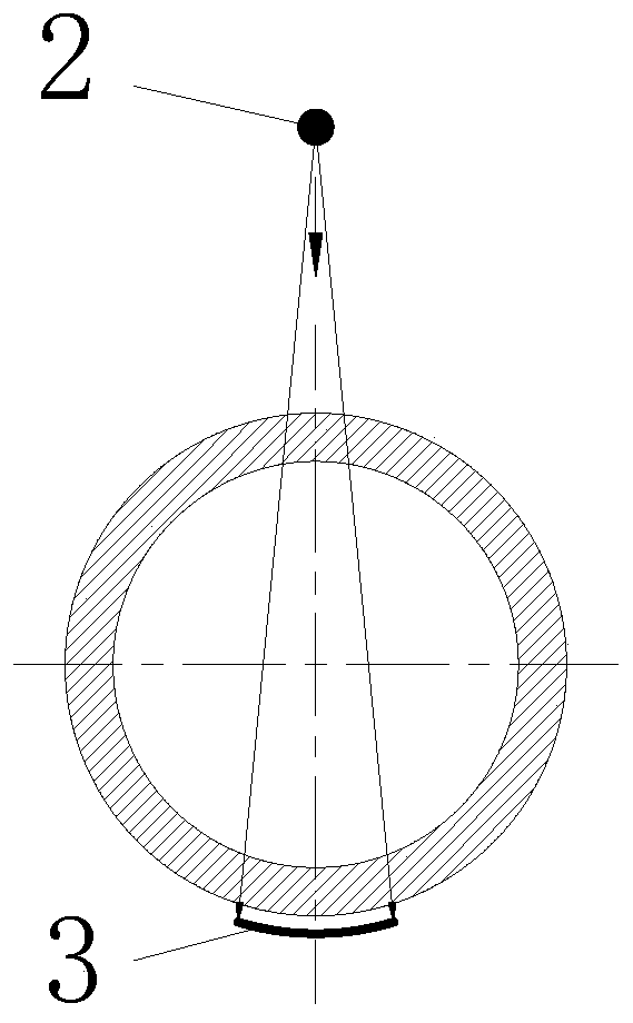
[0031]Embodiment 1 of the present invention: a non-destructive testing method for a thermal power plant pipeline weld seam, comprising the following steps: first, a flaw detection hole 15 is opened before the pipeline leaves the factory, and the distance between the axis of the flaw detection hole 15 and the edge of the weld bevel 1 is 120mm, use the equipment and instruments of the factory to ensure the precise standard of the flaw detection hole 15, and then extend the radiation source 2 from the flaw detection hole 15 into the pipeline. On the outside of the weld, the image on the negative film 3 can display the internal structure of the weld, turn on the radiation source 2, and perform radiographic flaw detection. After the flaw detection, take out the radiation source 2 from the flaw detection hole 15, and finally use the flaw detection hole sealing piece 16 to pair the flaw detection hole 15 for sealing, and the structures of the flaw detection hole 15 and the flaw detect...
Embodiment 2
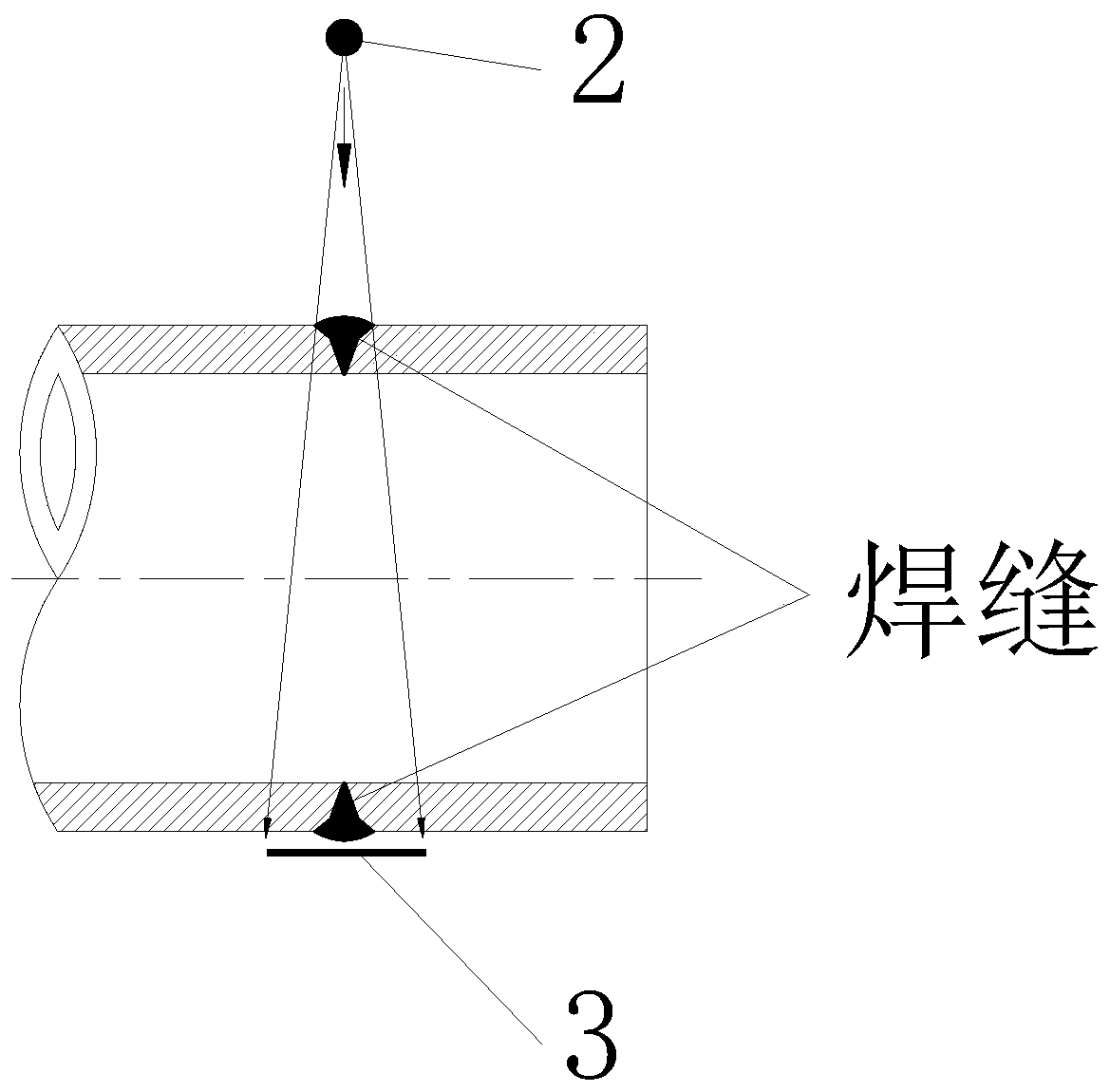
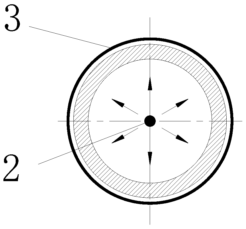
[0032] Embodiment 2 of the present invention: as image 3 or Figure 4 As shown, in the non-destructive testing method for thermal power plant pipeline welds according to the present invention, the working position of the radiation source 2 is located at the center of the section where the pipeline welds are located, which can ensure that the rays pass through the welds vertically and are irradiated on the negative film 3 , so that the image on the negative film 3 can correspond to the position of the weld seam one by one, making the flaw detection result more intuitive.
[0033] Embodiment 3 of the present invention: when performing non-destructive testing on pipeline welds with complex structures, the following steps are followed: first, after the pipeline welding is completed, a flaw detection hole 15 is opened at a position near the weld that does not affect the key structure of the pipeline, and the flaw detection The distance between the axis of the hole 15 and the edge...
Embodiment 5
[0035] Embodiment 5 of the present invention: According to the aforementioned non-destructive testing method for pipeline welds in thermal power plants, after the flaw detection process is completed, it is necessary to use the flaw detection hole plugging member 16 to seal the flaw detection hole 15. In order to achieve the sealing effect, the flaw detection hole is blocked After the flaw detection hole 15 is sealed by the flaw detection hole 15, it is also necessary to weld and fix the flaw detection hole blocking piece 16 and the outer wall of the pipeline.
[0036] Embodiment 6 of the present invention: as Image 6 or Figure 7 As shown, as mentioned above, the flaw detection hole 15 and the flaw detection hole blocking member 16 need to be adjusted according to the relationship between the design temperature of the pipeline and the creep temperature. Therefore, when the design temperature of the pipeline is below the creep temperature, the The flaw detection hole 15 on th...
PUM
 Abstract
Description
Claims
Application Information
 - R&D
- Intellectual Property
- Life Sciences
- Materials
- Tech Scout
- Unparalleled Data Quality
- Higher Quality Content
- 60% Fewer Hallucinations
Browse by: Latest US Patents, China's latest patents, Technical Efficacy Thesaurus, Application Domain, Technology Topic, Popular Technical Reports.
© 2025 PatSnap. All rights reserved.Legal|Privacy policy|Modern Slavery Act Transparency Statement|Sitemap|About US| Contact US: help@patsnap.com