Nanometer generator system and power supply device

A technology of nano generators and generators, applied in the direction of friction generators, etc., can solve problems affecting the life of devices, etc., and achieve the effects of wide application range, improved output effect, and high power output density

Active Publication Date: 2019-08-27
BEIJING INST OF NANOENERGY & NANOSYST
View PDF7 Cites 5 Cited by
  • Summary
  • Abstract
  • Description
  • Claims
  • Application Information

AI Technical Summary

Problems solved by technology

The surface electrostatic charge in the triboelectric nanogenerator is generated by friction or contact between two surfaces. Generally, severe friction or contact is easy to generate high charge density, but in this case, the surface is prone to greater heat and wear, which will greatly affect Device life; at the same time, the charge density is also constrained by air breakdown, which restricts the further improvement of the surface charge density and output power density

Method used


Image

  • Nanometer generator system and power supply device
  • Nanometer generator system and power supply device
  • Nanometer generator system and power supply device

Examples


Embodiment 1

[0053] In a first exemplary embodiment of the present disclosure, a contact-separated nanogenerator system including two floating layers is provided.

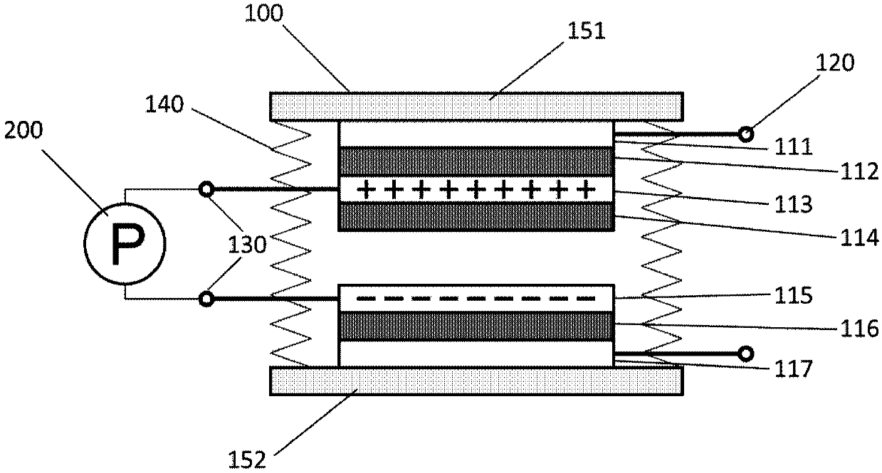
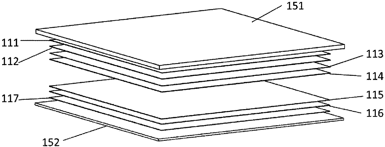
[0054] figure 1 It is a schematic structural diagram of a contact-separated nanogenerator system according to the first embodiment of the present disclosure. figure 2 It is a three-dimensional exploded view of the contact-separated floating structure according to the first embodiment of the present disclosure.

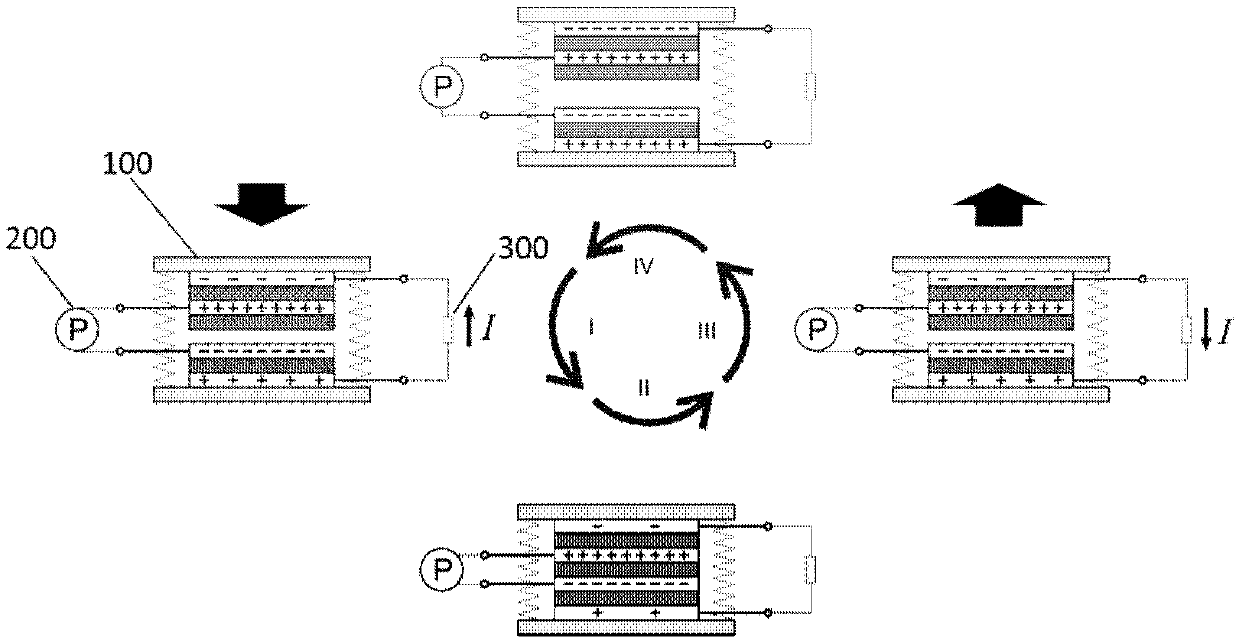
[0055] combine figure 1 and figure 2 As shown, the contact-separated nanogenerator system of this embodiment includes: a floating structure 100 and a charge pump 200 .

[0056] refer to figure 1 , figure 2As shown, in this embodiment, the floating structure 100 includes: a first substrate 151; on the first substrate 151, a first electrode layer 111, a first dielectric layer 112, a first floating layer 113, and The third dielectric layer 114 provided on the surface of the first floating layer 113; the second sub...

Embodiment 2

[0069] In a second exemplary embodiment of the present disclosure, an induction nanogenerator system including 2 floating layers is provided.

[0070] Figure 5 Schematic diagram of the structure of the inductive nanogenerator system. It includes: a floating structure and a charge pump 200 .

[0071] refer to Figure 5 As shown, in this embodiment, the floating structure includes: a first substrate 151; on the first substrate 151, a first floating layer 113 is sequentially disposed, and a third dielectric layer 114 is disposed on the surface of the first floating layer 113; The second substrate 152 is arranged opposite to the first substrate 151; on the second substrate 152, a discrete first electrode layer 111 and a second electrode layer 117 are sequentially arranged on the first electrode layer 111 and the second electrode layer 117 A first dielectric layer 112, a second dielectric layer 116, and a second floating layer 115 are respectively provided, and the first floati...

Embodiment 3

[0074] In a third exemplary embodiment of the present disclosure, a single-electrode nanogenerator system including 2 floating layers is provided.

[0075] Figure 6 Schematic diagram of the structure of a single-electrode nanogenerator system. It includes: a floating structure and a charge pump 200 .

[0076] refer to Figure 6 As shown, in this embodiment, the floating structure includes: a first substrate 151; a first floating layer 113, a third dielectric layer 114 and a second floating layer 115 are sequentially stacked on the first substrate 151; The second substrate 152 is arranged opposite to the first substrate 151; the second electrode layer 117 and the second dielectric layer 116 are sequentially stacked on the second substrate 152, and the first floating layer 113 and the second floating layer 115 are connected with the charge The pump 200 is connected; wherein, the second floating layer 115 and the second dielectric layer 116 are arranged opposite to each other...


PUM


Abstract

The invention discloses a nanometer generator system and a power supply device. The nanometer generator system comprises an electrode layer, a floating layer, a dielectric layer arranged on the uppersurface and/or the lower surface of the floating layer, and a charge pump connected with the floating layer and used for injecting charge into the floating layer; and the generator system outputs an electric signal to an external circuit when the floating layer moves relative to the electrode layer. The floating layer and a combination of the floating layer and the dielectric layer are used as equivalence of at least one friction layer with friction electrification and electrostatic charge storage functions; and the charge can be controllably injected into the floating layer in real time through the charge pump. The charge density of the nanometer generator system is no longer generated by mainly depending on friction or contact and is not restricted by air breakdown and the like; and thenanometer generator system has high power output density.

Description

technical field [0001] The disclosure belongs to the technical field of nano new energy and mechanical energy collection, and relates to a nano generator system and a power supply device. Background technique [0002] The basic principle of triboelectric nanopower generation technology is that when at least one of the two surfaces in contact or friction is an insulating material, friction or contact is used to induce static charges on the two surfaces. When the two surfaces in contact are separated, the separation of static charges A potential difference is generated, resulting in a directional movement of free charges in the sensing electrodes, so that the mechanical energy in the environment can be collected and converted into electrical energy. Frictional nano-power generation technology is especially suitable for collecting low-frequency mechanical energy. It has the advantages of simple structure, low cost, and rich material selection. It has potential application value...

Claims


Application Information

Patent Timeline
Patent Type & Authority Applications(China)
IPC IPC(8): H02N1/04
CPCH02N1/04
Inventor 许亮布天昭张弛其他发明人请求不公开姓名
Owner BEIJING INST OF NANOENERGY & NANOSYST
Why Eureka
Try Eureka