Nano generator system and power supply device
A technology of nano generators and generators, applied in the direction of friction generators, etc., can solve problems affecting the life of devices, etc., achieve a wide range of applications, promote practicality, and improve output effects
- Summary
- Abstract
- Description
- Claims
- Application Information
AI Technical Summary
Problems solved by technology
Method used
Image
Examples
Embodiment 1
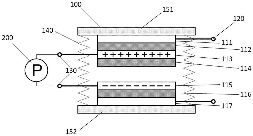
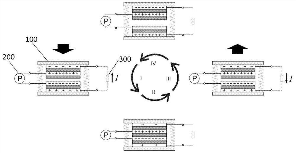
[0053] In a first exemplary embodiment of the present disclosure, a contact-separated nanogenerator system including two floating layers is provided.
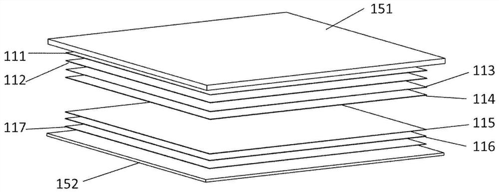
[0054] figure 1 It is a schematic structural diagram of a contact-separated nanogenerator system according to the first embodiment of the present disclosure. figure 2 It is a three-dimensional exploded view of the contact-separated floating structure according to the first embodiment of the present disclosure.
[0055] combine figure 1 and figure 2 As shown, the contact-separated nanogenerator system of this embodiment includes: a floating structure 100 and a charge pump 200 .
[0056] refer to figure 1 , figure 2As shown, in this embodiment, the floating structure 100 includes: a first substrate 151; on the first substrate 151, a first electrode layer 111, a first dielectric layer 112, a first floating layer 113, and The third dielectric layer 114 provided on the surface of the first floating layer 113; the second sub...
Embodiment 2
[0069] In a second exemplary embodiment of the present disclosure, an induction nanogenerator system including 2 floating layers is provided.
[0070] Figure 5 Schematic diagram of the structure of the inductive nanogenerator system. It includes: a floating structure and a charge pump 200 .
[0071] refer to Figure 5 As shown, in this embodiment, the floating structure includes: a first substrate 151; on the first substrate 151, a first floating layer 113 is sequentially disposed, and a third dielectric layer 114 is disposed on the surface of the first floating layer 113; The second substrate 152 is arranged opposite to the first substrate 151; on the second substrate 152, a discrete first electrode layer 111 and a second electrode layer 117 are sequentially arranged on the first electrode layer 111 and the second electrode layer 117 A first dielectric layer 112, a second dielectric layer 116, and a second floating layer 115 are respectively provided, and the first floati...
Embodiment 3
[0074] In a third exemplary embodiment of the present disclosure, a single-electrode nanogenerator system including 2 floating layers is provided.
[0075] Figure 6 Schematic diagram of the structure of a single-electrode nanogenerator system. It includes: a floating structure and a charge pump 200 .
[0076] refer to Figure 6 As shown, in this embodiment, the floating structure includes: a first substrate 151; a first floating layer 113, a third dielectric layer 114 and a second floating layer 115 are sequentially stacked on the first substrate 151; The second substrate 152 is arranged opposite to the first substrate 151; the second electrode layer 117 and the second dielectric layer 116 are sequentially stacked on the second substrate 152, and the first floating layer 113 and the second floating layer 115 are connected with the charge The pump 200 is connected; wherein, the second floating layer 115 and the second dielectric layer 116 are arranged opposite to each other...
PUM
| Property | Measurement | Unit |
|---|---|---|
| thickness | aaaaa | aaaaa |
| thickness | aaaaa | aaaaa |
Abstract
Description
Claims
Application Information
 - R&D
- Intellectual Property
- Life Sciences
- Materials
- Tech Scout
- Unparalleled Data Quality
- Higher Quality Content
- 60% Fewer Hallucinations
Browse by: Latest US Patents, China's latest patents, Technical Efficacy Thesaurus, Application Domain, Technology Topic, Popular Technical Reports.
© 2025 PatSnap. All rights reserved.Legal|Privacy policy|Modern Slavery Act Transparency Statement|Sitemap|About US| Contact US: help@patsnap.com


