
A vertical shaft impact sand making machine

A technology of vertical shaft impact and sand making machine, applied in the field of mining equipment, can solve the problems of dust pollution, large productive dust, single structure of crushing chamber assembly, etc. The effect of efficiency

Active Publication Date: 2021-08-06
ZAOZHUANG SNKSAN INTELLIGENT MACHINERY CO LTD
View PDF9 Cites 0 Cited by
  • Summary
  • Abstract
  • Description
  • Claims
  • Application Information

AI Technical Summary

Problems solved by technology

[0003] However, in the existing vertical shaft impact sand making machine, the structure of the crushing chamber assembly is single, the crushing efficiency of the sand making machine is reduced, and at the same time, the flow of materials cannot be adjusted, resulting in the inability to adjust the flow of throwing and blanking in daily use. , cannot meet different crushing needs, and the existing sand making machine will generate a large amount of dust due to the high-speed movement of the rotor during the crushing process, and the productive dust generated is too large, causing dust pollution and affecting the health of construction workers. Therefore, in view of the above status quo , there is an urgent need to develop a vertical shaft impact sand making machine to overcome the deficiencies in current practical applications

Method used


Image

  • A vertical shaft impact sand making machine
  • A vertical shaft impact sand making machine
  • A vertical shaft impact sand making machine

Examples


Embodiment 1

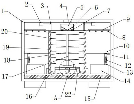
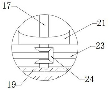
[0023] see Figure 1~3 , in an embodiment of the present invention, a vertical shaft impact sand making machine includes a shell 1, a feed port 4, a feed hopper 5 and a crushing chamber 19, the feed port 4 is arranged on the top of the shell 1, and the feed port 4 A feed hopper 5 is provided on the lower side, and a crushing chamber 19 is provided on the lower side of the feed hopper 5. The left and right sides of the bottom of the crushing chamber 19 are provided with fixed blocks 16 fixedly connected to the shell 1. The crushing chamber 19 is connected to the The fixed block 16 is slidably connected, dust removal devices are arranged on both sides of the crushing chamber 19 , and a shock absorbing pad 15 is arranged at the bottom of the fixed block 16 .

[0024] In this embodiment, the feed hopper 5 includes a first telescopic rod 2, a push plate 3, a telescopic plate 6 and a second telescopic rod 7, the telescopic plate 6 is arranged at both ends of the inner side of the fe...

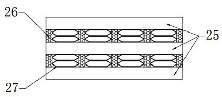
Embodiment 2

[0030] A mining equipment includes the vertical shaft impact sand making machine described in Embodiment 1.

[0031] The vertical shaft impact sand making machine can realize the adjustment of the throwing material flow rate by setting the second telescopic rod 7 and the telescopic plate 6. By controlling the first telescopic rod 2, the blanking material flow rate can be adjusted. By setting the dust removal device, the system is effectively solved. The problem of excessive dust in the crushing process of the sand machine can realize the function of reducing dust. By setting the first filter layer 11 and the second filter layer 12, the purification of dust removal water can be realized, and the recycling of water resources can be realized. Through the motor 22, The shaft 17 and the crushing cavity 19 can rotate in the opposite direction, which is beneficial to improve the crushing efficiency of the sand making machine. By intersecting the metal plate 25, the elastic pad 26 and ...


PUM


Abstract

The invention relates to the field of mining equipment, in particular to a vertical shaft impact sand making machine, which includes a casing, a feeding port, a feeding hopper and a crushing chamber. The lower side is provided with a crushing chamber, the left and right sides of the bottom of the crushing chamber are provided with fixed blocks fixedly connected with the casing, dust removal devices are provided on both sides of the crushing chamber, and shock absorbing pads are provided at the bottom of the fixed block. In the present invention, by setting the feeding hopper , can realize the adjustment of the throwing and blanking flow rate, and effectively solve the problem of excessive dust in the crushing process of the sand making machine by setting the dust removal device, and can realize the dust removal water by setting the first filter layer and the second filter layer Purify and realize the recycling of water resources. Through the motor, the rotating shaft and the crushing cavity can rotate in the opposite direction, which is beneficial to improve the crushing efficiency of the sand making machine.

Description

technical field [0001] The invention relates to the field of mining equipment, in particular to a vertical shaft impact sand making machine. Background technique [0002] In the field of mining equipment, vertical shaft impact crusher is also known as sand making machine. Production of mountain rocks (limestone, granite, basalt, diabase, andesite, etc.), ore tailings, artificial sand from stone chips, construction aggregates, road fabrics, cushion materials, asphalt concrete and cement concrete aggregates, and various Fine crushing and coarse grinding of various metallurgical slags, especially for medium-hard, extra-hard and abrasive materials such as silicon carbide, corundum, sintered bauxite, magnesia, etc. The main shaft group drives the rotor group to rotate at a high speed, and the rotor group throws the middle part of the material at a high speed inside the crushing cavity assembly and collides with the surrounding blanking materials, through "rock hitting rock" and ...

Claims


Application Information

Patent Timeline
Patent Type & Authority Patents(China)
IPC IPC(8): B02C18/12B02C18/22B02C18/16B01D36/02B01D47/06
CPCB01D36/02B01D47/06B02C18/12B02C18/16B02C18/2291
Inventor 孙启祥马驰孙法虎
Owner ZAOZHUANG SNKSAN INTELLIGENT MACHINERY CO LTD
Learn More