Double-sided cleaning device for veterinary equipment

A technology for cleaning equipment and equipment, which is applied in the field of double-sided cleaning equipment for veterinary equipment, and can solve problems affecting treatment, etc.

Inactive Publication Date: 2019-08-30
贾桂兰 +6
View PDF9 Cites 5 Cited by
  • Summary
  • Abstract
  • Description
  • Claims
  • Application Information

AI Technical Summary

Problems solved by technology

However, in the process of cleaning and drying, only one side of the tool can be rinsed and dried, and the other side needs to be sent to the int

Method used


Image

  • Double-sided cleaning device for veterinary equipment
  • Double-sided cleaning device for veterinary equipment
  • Double-sided cleaning device for veterinary equipment

Examples


Embodiment 1

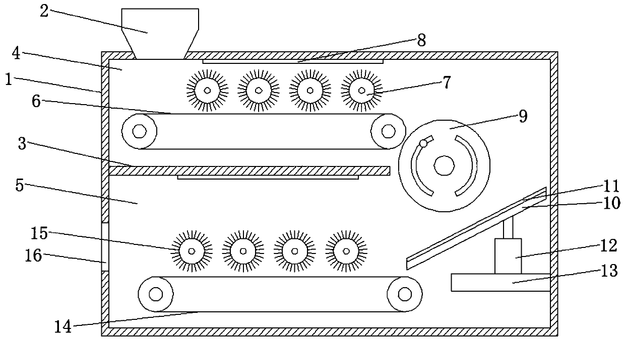
[0019] Please refer to the figure, in the embodiment of the present invention, a double-sided cleaning equipment for veterinary equipment includes a box body 1, a filling port 2, a partition 3 and an outlet 16; the filling port 2 is arranged at the top left end of the box body 1, The veterinary equipment is loaded into the box body 1 from the filling port 2; a horizontal partition 3 is fixedly installed on the inner wall on the left side of the box body 1, and the partition plate 3 is located in the middle, and the box body 1 is divided into upper and lower parts. Two chambers are respectively the first cleaning chamber 4 and the second cleaning chamber 5. The right end of the partition plate 3 is not connected to the other side wall of the box body 1, so that the right side of the partition plate 3 is a communication port, and the first cleaning chamber The cavity 4 and the second cleaning cavity 5 are in communication.

[0020] The first cleaning chamber 4 is provided with a...

Embodiment 2

[0024] On the basis of Embodiment 1, a layer of sponge layer 11 is laid on the upper surface of the slant plate 10, so that the instrument can scrub its lower surface during the process of sliding down, and the lower side of the slant plate 10 is fixedly connected with a The height adjustment device 12 on the top, the height adjustment device 12 is a hydraulic cylinder structure, the height adjustment device 12 is fixed by the support seat 13, the height of the swash plate 10 is adjusted through the height adjustment device 12, and it is adjusted for different volumes of equipment, so that the lower end It is smoother on the second conveyor belt 14 .

[0025]Put the veterinary equipment into the box body 1 from the loading port 2, drop it on the first conveyor belt 6 in the first cleaning chamber 4, transport it to the right through the first conveyor belt 6, and brush it through the first cleaning roller 7 , the right end of the first conveying belt 6 of the instrument falls ...


PUM


Abstract

The invention relates to the veterinary field, in particular to a double-sided cleaning device for veterinary equipment. The double-sided cleaning device for the veterinary equipment comprises a box body, a filling port, a partition plate and an outlet; the right end of the partition plate is provided with a turnover mechanism rotating in the horizontal direction, the turnover mechanism comprisesa turnover roller, static contacts, contact support plates, elastic blocks, electromagnets and conductive grooves, and the arc surface of the turnover roller is covered with the two electromagnets; the conductive grooves corresponding to the electromagnets one to one are formed in each of the front end and the rear end of the turnover roller, and the corresponding electromagnets are electrically connected in the conductive grooves; and the static contacts are correspondingly arranged on the outer sides of the conductive grooves on the two sides of the turnover roller, and the static contacts extend into the conductive grooves. According to the double-sided cleaning device, the equipment is scrubbed through cleaning rollers, and the turnover mechanism can overturn the equipment in the cleaning process to enable the other side of the equipment to be upward, so that the two sides of the equipment are continuously scrubbed, the equipment is scrubbed thoroughly, overturning of the equipmentis automatically controlled, especially for iron equipment, manual operation is not required, and time and labor are saved.

Description

technical field [0001] The invention relates to the field of veterinary medicine, in particular to a double-sided cleaning device for veterinary equipment. Background technique [0002] A veterinarian is a doctor who prevents, diagnoses, and treats diseases for animals. With the progress of society and the development of veterinary science, veterinarians are designed to treat the pathogens, pathology, diagnosis, treatment, and prevention of animal diseases. During treatment, tools need to be used. According to the requirements of health management, veterinarians need to clean, disinfect and sterilize the tools. [0003] In the prior art, the tools used by veterinarians are generally cleaned first, and then cleaned by high temperature or disinfectant. The cleaning and disinfection are carried out in different equipment, and both need to be done manually, which is laborious and laborious. Chinese patent (notification number: CN 208928649 U) discloses a veterinary cleaning dev...

Claims


Application Information

Patent Timeline
IPC IPC(8): B08B1/02B08B3/02B08B13/00
CPCB08B1/02B08B3/022B08B13/00
Inventor 李静
Owner 贾桂兰
Why Eureka
Try Eureka