
Rotary body clamping and positioning jig and cutting machine

A technology of clamping and positioning, rotating body, applied in the direction of manufacturing tools, welding equipment, laser welding equipment, etc., can solve the problems of laser cutting and processing of difficult-to-rotate workpieces

Active Publication Date: 2019-08-30
BEIJING SEMICON EQUIP INST THE 45TH RES INST OF CETC
View PDF6 Cites 2 Cited by
  • Summary
  • Abstract
  • Description
  • Claims
  • Application Information

AI Technical Summary

Problems solved by technology

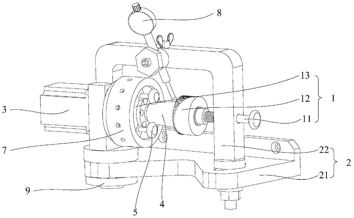
[0003] The purpose of this application is to provide a rotary body clamping and positioning jig and cutting machine to solve the technical problem existing in the prior art that it is difficult to perform laser cutting on rotary body workpieces

Method used


Image

  • Rotary body clamping and positioning jig and cutting machine
  • Rotary body clamping and positioning jig and cutting machine
  • Rotary body clamping and positioning jig and cutting machine

Examples


Embodiment Construction

[0029] The technical solutions of the present application will be clearly and completely described below in conjunction with the accompanying drawings. Apparently, the described embodiments are some of the embodiments of the present application, not all of them.

[0030] The components of the embodiments of the application generally described and shown in the figures herein may be arranged and designed in a variety of different configurations. Accordingly, the following detailed description of the embodiments of the application provided in the accompanying drawings is not intended to limit the scope of the claimed application, but merely represents selected embodiments of the application.

[0031] Based on the embodiments in this application, all other embodiments obtained by persons of ordinary skill in the art without making creative efforts belong to the scope of protection of this application.

[0032] In the description of this application, it should be noted that the ter...


PUM


Abstract

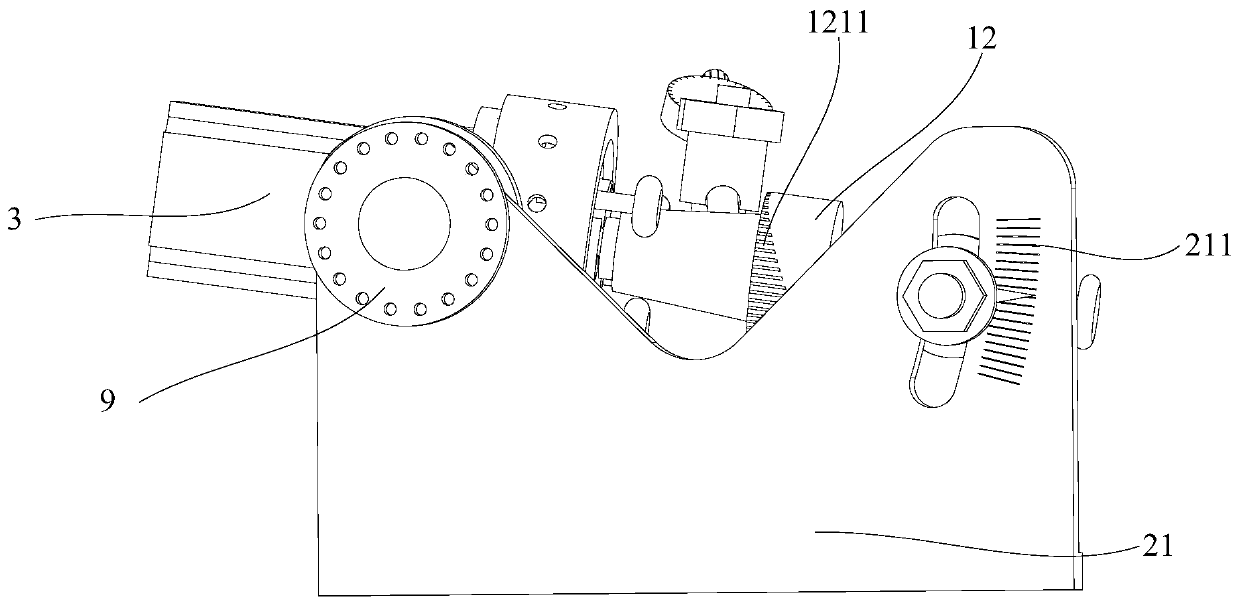
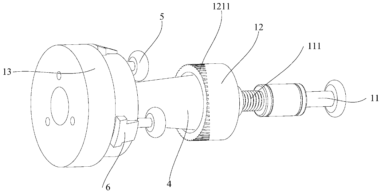
The invention relates to the technical field of laser cutting machining, in particular to a rotary body clamping and positioning jig and a cutting machine. The rotary body clamping and positioning jigcomprises a supporting component, a clamping component and a driving device; the clamping component comprises a pulling-pressing part, a aligning device and a fixing disc; the pulling-pressing part is connected with the aligning device; a plurality of positioning parts are arranged on the fixing disc, and a rotary body workpiece is clamped between the aligning device and the fixing disc and is positioned in a limiting space enclosed by the plurality of positioning parts; and the output end of the driving device is arranged at the center of the fixing disc in a penetrating mode. According to the rotary body clamping and positioning jig, the output end of the driving device, the axis of the rotary body workpiece, the central axis of the aligning device and the pulling-pressing part are located on the same straight line, so that the distance between the machining surface of the rotary body workpiece and a laser lens is fixed; and the driving device is started, the output end of the driving device drives the rotary body workpiece to rotate, so that the surface of the rotary body workpiece can be uniformly cut.

Description

technical field [0001] The present application relates to the technical field of laser cutting, in particular to a clamping and positioning jig for a revolving body and a cutting machine. Background technique [0002] Laser cutting process is to use high-energy-density laser beam to act on the target, so that the target surface generates enough heat to melt the material, and the high-pressure gas coaxial with the beam directly removes the molten material, so as to achieve the purpose of cutting. The lens of the laser processing equipment must keep a certain distance from the workpiece, and the appearance characteristics of the rotary body cannot meet the requirements of laser processing, so it is difficult to perform laser cutting on the rotary body workpiece. Based on this objective requirement, a special fixture is needed to Keep a fixed distance between the surface processing area of ​​the rotating body and the laser lens. Contents of the invention [0003] The purpose...

Claims


Application Information

Patent Timeline
IPC IPC(8): B23K26/38B23K26/08B23K26/03
CPCB23K26/032B23K26/0823B23K26/38
Inventor 田世伟王洪宇武震
Owner BEIJING SEMICON EQUIP INST THE 45TH RES INST OF CETC
Learn More