Supercharge Your Innovation With Domain-Expert AI Agents!

Extruder cooling system

A technology of cooling system and extruder, applied in the field of extrusion transportation, can solve the problems of poor adjustment performance, no energy saving, and inability to quickly adjust temperature, so as to achieve the effect of reducing consumption and improving heat exchange effect

Pending Publication Date: 2019-08-30
佛山智塑科技有限公司
View PDF0 Cites 2 Cited by
  • Summary
  • Abstract
  • Description
  • Claims
  • Application Information

AI Technical Summary

Problems solved by technology

[0002] The extruder includes a stator and a screw-type rotor. The rotor is rotatably installed in the stator. The two ends of the stator are respectively provided with a material inlet and a material outlet. Driven by the power source, the stator is driven by the rotor and the stator. , the material can be pushed and extruded from the feed port to the discharge port. During the process of pushing and extruding, the extruder is cooled or heated according to the needs of processing different materials. The commonly used cooling methods for existing extruders are: Water-cooled and air-cooled, some also use oil-cooled, no matter water-cooled, air-cooled or oil-cooled, it is necessary to install a cooling water tank for heat exchange, which will increase the space and cost of the equipment, high energy consumption, not energy-saving, in polymer In the processing of material molding, the temperature of each extrusion section is different. Existing systems use multiple sets of cooling devices to cool the extruder to achieve temperature control for each extrusion section. However, the existing extrusion The cooling system of the machine also has the problem of poor adjustment performance. There is a certain delay in temperature control, and it cannot be adjusted to a certain temperature quickly.

Method used


Image

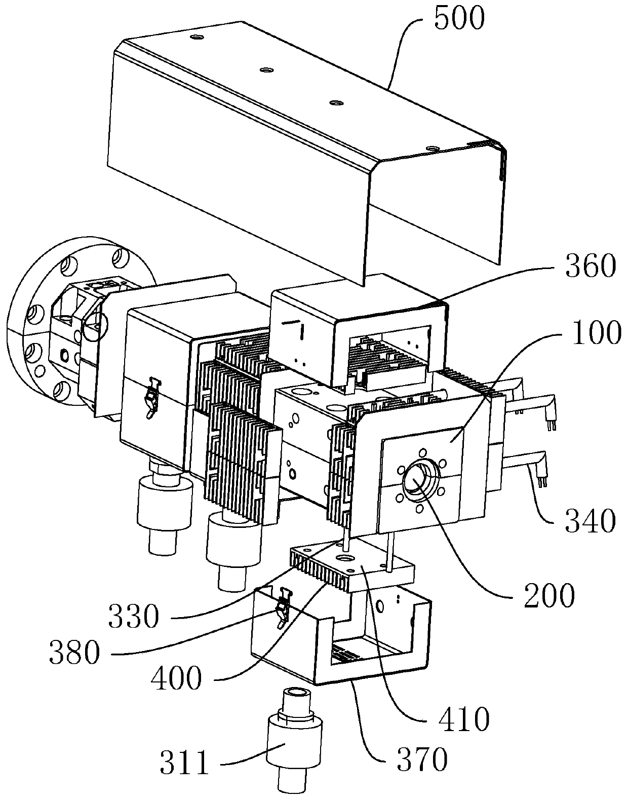
  • Extruder cooling system
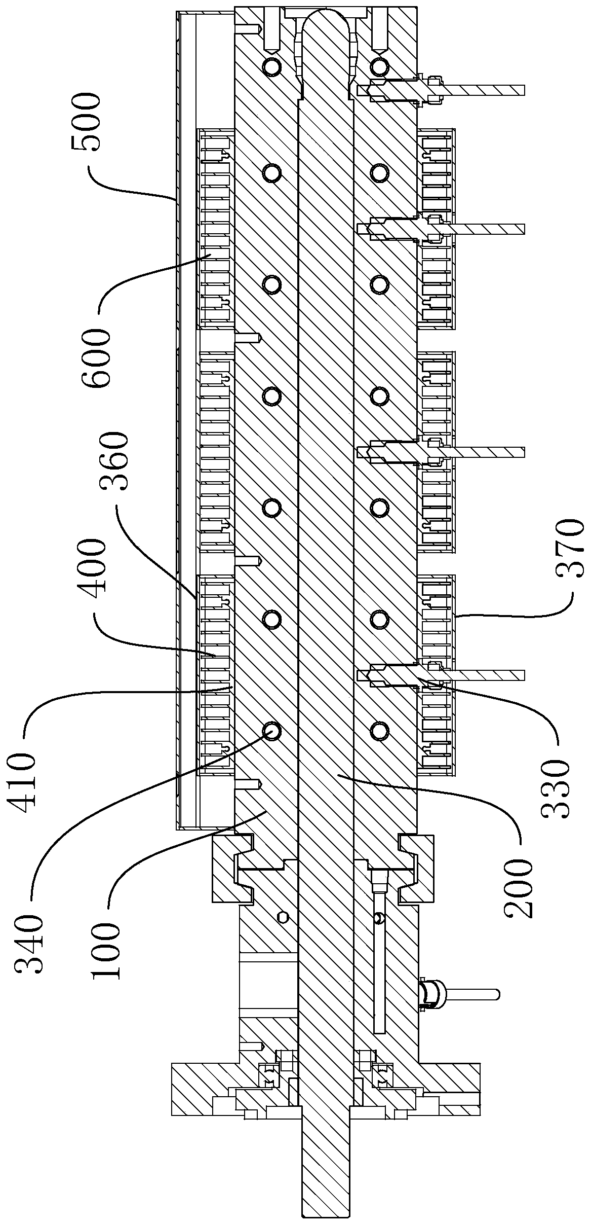
  • Extruder cooling system
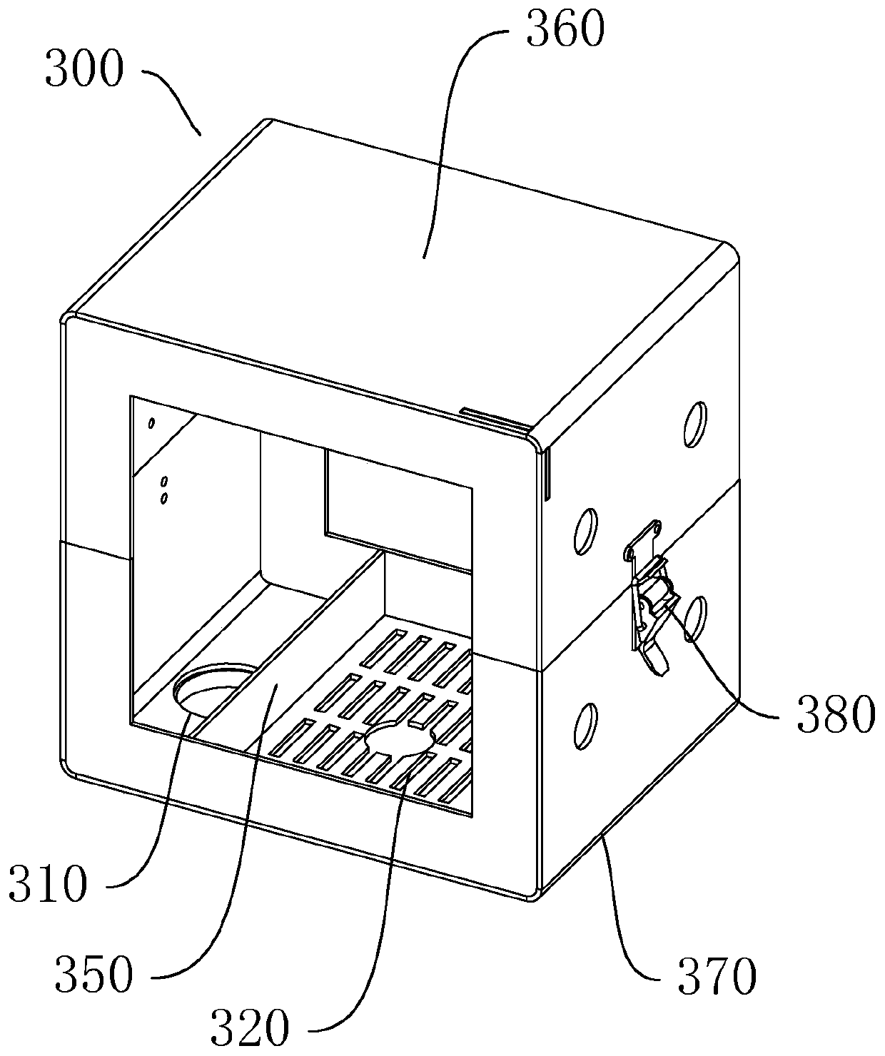
  • Extruder cooling system

Examples


Embodiment Construction

[0021] The idea, specific structure and technical effects of the present invention will be clearly and completely described below in conjunction with the embodiments and accompanying drawings, so as to fully understand the purpose, features and effects of the present invention. Apparently, the described embodiments are only some of the embodiments of the present invention, rather than all of them. Based on the embodiments of the present invention, other embodiments obtained by those skilled in the art without creative efforts belong to The protection scope of the present invention. In addition, all the connection / connection relationships mentioned in this article do not refer to the direct connection of components, but mean that a better connection structure can be formed by adding or reducing connection accessories according to specific implementation conditions. The various technical features in the present invention can be combined interactively on the premise of not confli...


PUM


Abstract

The invention discloses an extruder cooling system. The extruder cooling system comprises an air supply device, a stator extending leftwards and rightwards, and a rotor rotatably mounted in the statorand extending leftwards and rightwards. A plurality of cooling mechanisms are arranged outside the stator in a sleeving mode and are distributed in a spaced mode in the left-right direction. Each cooling mechanism comprises a fan cover body matched with the stator in size and shape. The fan cover bodies are arranged on the periphery of the stator in a sleeving mode, and a cooling cavity is formedby the fan cover bodies and the outer side face of the stator. Air inlets and air outlets which communicate with the cooling cavity are formed in the walls of the fan cover bodies. The air inlets areconnected with air amplifiers. The air supply device is connected with the air amplifiers. The pressure of cooling air from the air supply device is amplified through the air amplifiers, then the cooling air enters the cooling cavity to cool the stator, and finally, the cooling air is exhausted via the air outlets; and different extrusion sections of the stator are cooled through the multiple cooling mechanisms, so that the cooling effect is flexibly adjusted. The extruder cooling system is used for regulating and controlling the temperatures of the extrusion sections of an extruder.

Description

technical field [0001] The invention relates to the field of extrusion conveying, in particular to an extruder cooling system. Background technique [0002] The extruder includes a stator and a screw-type rotor. The rotor is rotatably installed in the stator. The two ends of the stator are respectively provided with a material inlet and a material outlet. Driven by the power source, the stator is driven by the rotor and the stator. , the material can be pushed and extruded from the feed port to the discharge port. During the process of pushing and extruding, the extruder is cooled or heated according to the needs of processing different materials. The commonly used cooling methods for existing extruders are: Water-cooled and air-cooled, some also use oil-cooled, no matter water-cooled, air-cooled or oil-cooled, it is necessary to install a cooling water tank for heat exchange, which will increase the space and cost of the equipment, high energy consumption, not energy-saving...

Claims


Application Information

Patent Timeline
IPC IPC(8): B29C48/85B29C48/84B29C48/92
CPCB29C48/85B29C48/845B29C48/92B29C2948/92209B29C2948/92704
Inventor 曾艳祥覃健召刘承贵李保银姚昆亮陈春铭
Owner 佛山智塑科技有限公司
Features
  • R&D
  • Intellectual Property
  • Life Sciences
  • Materials
  • Tech Scout
  • Unparalleled Data Quality
  • Higher Quality Content
  • 60% Fewer Hallucinations
Learn More