Overturning sliding cavity door structure, plasma vacuum cavity and plasma treatment equipment

A processing equipment, sliding technology, applied in the direction of gaseous chemical plating, metal material coating process, discharge tube, etc., can solve the problems of production requirements that cannot meet the increasing demand, low production process efficiency, etc., to achieve replacement and maintenance. Effects of a vacuum environment

Pending Publication Date: 2019-08-30
SUZHOU WEIPENG ELECTRICAL TECH CO LTD
View PDF0 Cites 4 Cited by
  • Summary
  • Abstract
  • Description
  • Claims
  • Application Information

AI Technical Summary

Problems solved by technology

[0002] The vacuum chamber is an essential part of many processing equipment. In the existing vacuum chamber, one side of most vacuum chamber doors is hinged on the side wall of the chamber body. When changing the incoming and outgoing materials, open the vacuum The chamber door is generally used to take out the materials in the vacuum chamber first, and then put the materials to be processed into the vacuum chamber. The efficiency of the entire production process is low and cannot meet the increasing production requirements.

Method used


Image

  • Overturning sliding cavity door structure, plasma vacuum cavity and plasma treatment equipment
  • Overturning sliding cavity door structure, plasma vacuum cavity and plasma treatment equipment
  • Overturning sliding cavity door structure, plasma vacuum cavity and plasma treatment equipment

Examples


Embodiment 1

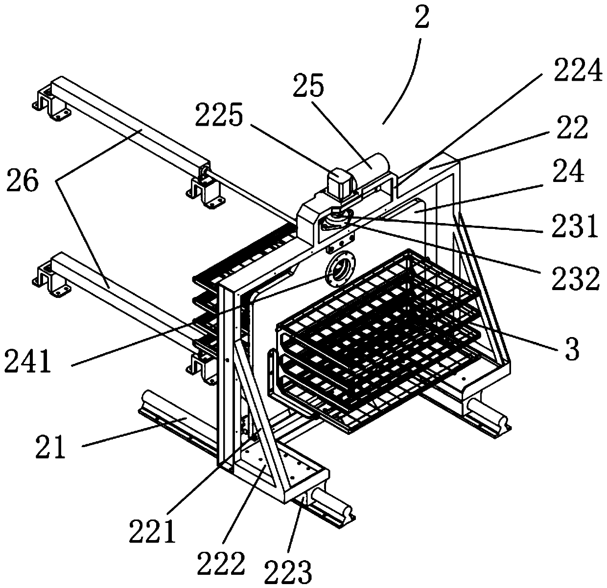
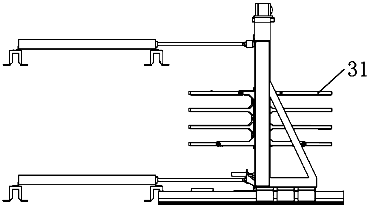
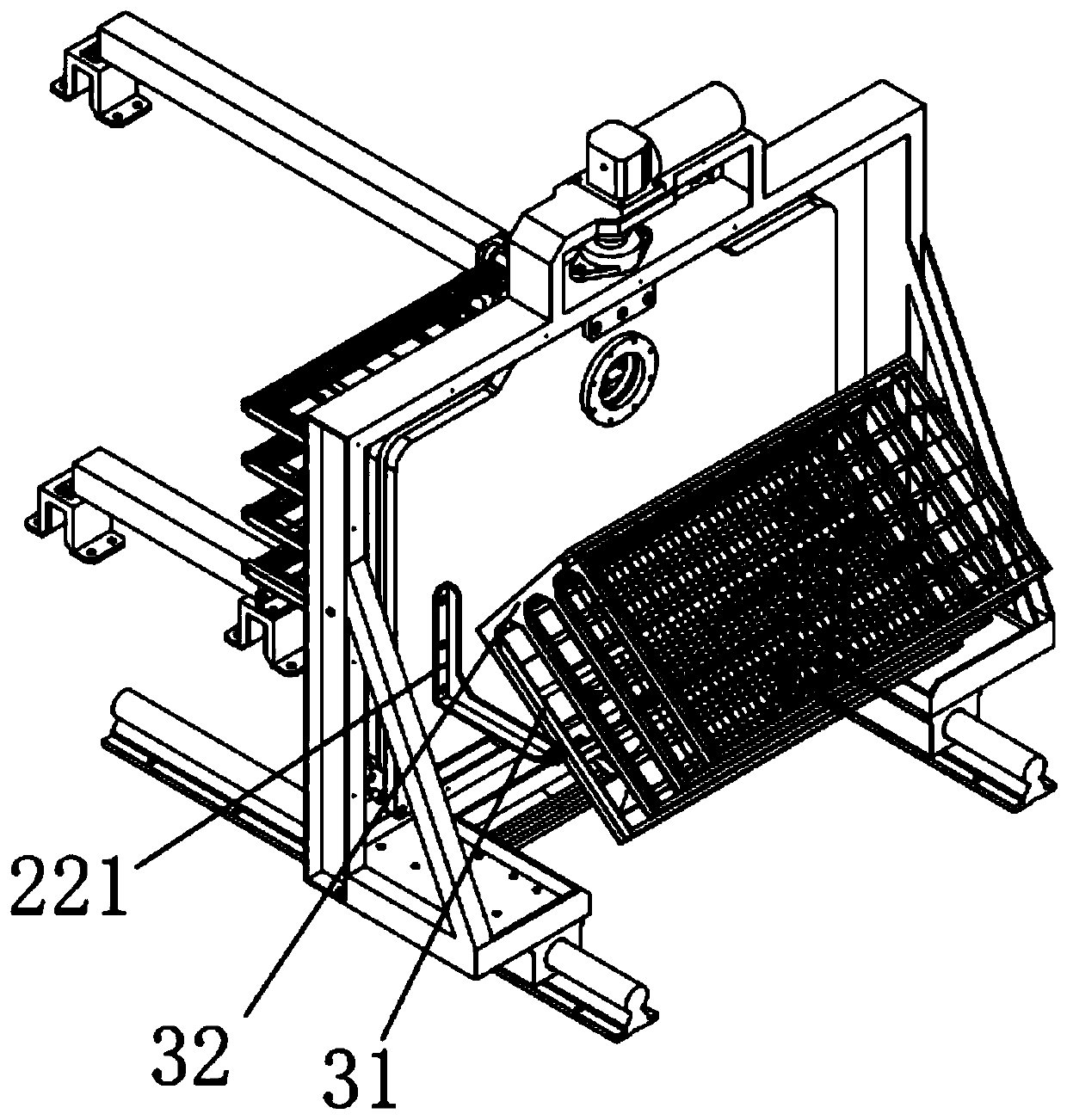
[0031] The present invention provides a flip-sliding cavity door structure 2, such as Figure 1-3 Said, including slide rail 21, the installation frame 22 that is slidably installed on the slide rail 21 and the chamber door 24 that is rotatably connected to the inside of the installation frame 22, the chamber door 24 both sides are provided with material shelf tray 3, and the chamber door 24 middle part wears There is a vertical rotation shaft 231, and the vertical rotation shaft 231 is installed inside the installation frame 22. The vertical rotation shaft 231 is driven by the driving mechanism A25 located at the top of the installation frame 22. The rotating shaft 231 rotates inside the installation frame 22, and the installation frame 22 is driven to slide by the driving mechanism B26 located outside it.

[0032] Preferably, both ends of the vertical rotating shaft 231 pass through the chamber door 24 and are mounted on the top and bottom ends of the installation frame 22 t...

Embodiment 2

[0041] The invention provides a vacuum cavity, such as Figure 4-5 As shown, the cavity body 1 and the cavity door structure 2 are included. The cavity door structure 2 is any one of the cavity door structures in the embodiment 1. The edge of the inlet and outlet 11 of the cavity body is provided with a sealing ring 12. The sliding door structure of the cavity The rail is perpendicular to the plane where the entrance and exit of the chamber body are located, and the installation frame is fixed on the outside of the entrance and exit, and is parallel to the plane where the entrance and exit are located. The shape of the chamber door matches the entrance and exit. Under the action of the driving mechanism B, the door structure makes the door and the inlet and outlet closely fit, and the inner wall of the chamber body and the door form a vacuum chamber. The chamber door can be rotated 360° in the horizontal direction along the vertical rotation axis in the installation frame, so ...

Embodiment 3

[0046] The present invention provides a plasma vacuum chamber. On the basis of the vacuum chamber provided in Embodiment 2, a positive pole and a negative pole that are relatively distributed and connected to an external power supply are added inside the chamber body. The positive pole and the negative pole are located in the chamber body. At the top and bottom of the inner side, the positive and negative electrodes are energized to generate plasma; or, the cavity body is not provided with positive and negative electrodes, and can be directly connected to an external plasma generator, and the external plasma generator can generate plasma directly. Fill in the vacuum chamber.


PUM


Abstract

The invention discloses an overturning sliding cavity door structure, a plasma vacuum cavity and plasma treatment equipment. The cavity door structure comprises a slide rail, a mounting rack slidablymounted on the slide rail and a cavity door rotatably connected in the mounting rack. Material rest trays are arranged on two sides of the cavity door, a vertical rotating shaft is mounted in the middle of the cavity door in a penetrating manner, the vertical rotating shaft is mounted in the mounting rack, and the vertical rotating shaft is driven by a driving mechanism A located on the top of themounting rack, the cavity door under the action of the driving mechanism A rotates in the mounting rack around the vertical rotating shaft, and the mounting rack is driven by an external driving mechanism B to slide; and the plasma vacuum cavity and the plasma treatment equipment adopt the overturning sliding cavity door structure. By arranging the rotary vacuum cavity door, the positions of thematerial rest trays can be exchanged, so that a purpose of changing in-out materials quickly is further achieved.

Description

technical field [0001] The invention relates to the field of vacuum technology, in particular to a flip-sliding chamber door structure, a plasma vacuum chamber and plasma processing equipment. Background technique [0002] The vacuum chamber is an essential part of many processing equipment. In the existing vacuum chamber, one side of most vacuum chamber doors is hinged on the side wall of the chamber body. When changing the incoming and outgoing materials, open the vacuum The chamber door is generally used to take out the material in the vacuum chamber first, and then put the material to be processed into the vacuum chamber. The efficiency of the entire production process is low and cannot meet the increasing production requirements. Contents of the invention [0003] In order to solve the above problems, the object of the present invention is to provide a flip-sliding chamber door structure and a plasma vacuum chamber and plasma processing equipment utilizing the flip-sl...

Claims


Application Information

Patent Timeline
Patent Type & Authority Applications(China)
IPC IPC(8): C23C16/54H01J37/32
CPCC23C16/54H01J37/32458
Inventor 蔡刚强王琛璐
Owner SUZHOU WEIPENG ELECTRICAL TECH CO LTD
Why Eureka
Try Eureka