
Binding structure, binding method, display panel, and display device

A display panel and display device technology, which is applied in the direction of electrical components, electric solid-state devices, circuits, etc., and can solve problems such as unfavorable high resolution of display panels

Inactive Publication Date: 2019-08-30
GUANGZHOU GOVISIONOX TECH CO LTD
View PDF8 Cites 8 Cited by
  • Summary
  • Abstract
  • Description
  • Claims
  • Application Information

AI Technical Summary

Problems solved by technology

The current binding structure and binding method are not conducive to the realization of high-resolution display panels

Method used


Image

  • Binding structure, binding method, display panel, and display device
  • Binding structure, binding method, display panel, and display device

Examples


Embodiment Construction

[0026] In order to facilitate the understanding of the present invention, the present invention will be described more fully below with reference to the associated drawings. Preferred embodiments of the invention are shown in the accompanying drawings. However, the present invention can be embodied in many different forms and is not limited to the embodiments described herein. On the contrary, these embodiments are provided to make the understanding of the disclosure of the present invention more thorough and comprehensive.

[0027] It should be noted that when an element is referred to as being “fixed” to another element, it can be directly on the other element or there can also be an intervening element. When an element is referred to as being "connected to" another element, it can be directly connected to the other element or intervening elements may also be present. The terms "vertical," "horizontal," "left," "right," and similar expressions are used herein for purposes ...


PUM


Abstract

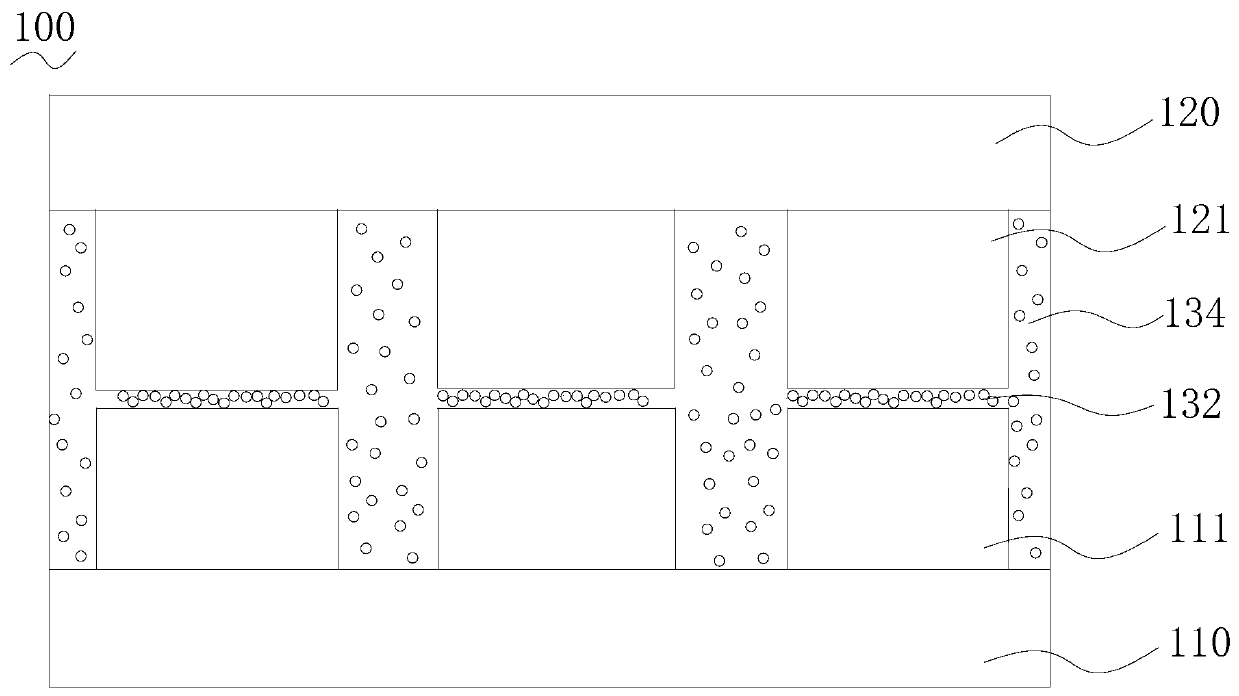
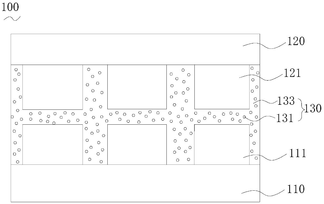
The invention relates to a binding structure, a binding method, a display panel, and a display device. The binding structure includes a first binding member, a second binding member, and a UV conductive adhesive disposed between a first binding terminal and a corresponding second binding terminal and in an area between the first and second binding members and where the first and second binding terminals are absent. The UV conductive adhesive comprises an ultraviolet curing adhesive and conductive particles distributed in the ultraviolet curing adhesive. The UV conductive paste is configured toprovide an electrical conduction path between the corresponding bonding terminals through the conductive particles under the effect of the ultraviolet light and the pressing force between the first and second binding members, and to form an insulating bonding layer in the area where the binding terminals are absent through the ultraviolet curing adhesive. The binding structure can be fabricated without heating or high-temperature heat treatment, thereby reducing or avoiding the problem that the high temperature of the existing anisotropic conductive adhesive hot-pressing treatment causes theterminal misalignment, and facilitating the realization of high resolution of the display panel.

Description

technical field [0001] The invention relates to the display field, in particular to a binding structure, a binding method, a display panel and a display device. Background technique [0002] With the continuous development of virtual reality display technology (virtual reality, VR) and mobile phone equipment, its requirements for the resolution of the display screen (Pixels per inch, PPI) are also continuously improving. The higher the PPI value, the higher the pixel resolution. High means that the display screen can display images with a higher density to obtain higher picture fidelity and fineness of the picture, thereby improving user experience. However, the higher the resolution of the display panel, the narrower the pixel gap is, which puts forward higher requirements for the bonding of the external driving circuit and the substrate of the display panel. The current binding structure and binding method are not conducive to the realization of high-resolution display pa...

Claims


Application Information

Patent Timeline
IPC IPC(8): H01L23/488H01L21/60H01L27/32
CPCH01L24/32H01L24/83H01L2224/32225H01L2224/8322H10K59/1275
Inventor 柴东亚李素华
Owner GUANGZHOU GOVISIONOX TECH CO LTD
Learn More