Supercharge Your Innovation With Domain-Expert AI Agents!

Cleaning device for gear machining

A technology for cleaning devices and gears, applied in liquid cleaning methods, dry gas layout, lighting and heating equipment, etc., can solve the problems of poor contact of gears, uneven dispersion, and influence on carbon content on the surface, so as to avoid the impact Effect

Inactive Publication Date: 2019-09-03
田锦海
View PDF6 Cites 0 Cited by
  • Summary
  • Abstract
  • Description
  • Claims
  • Application Information

AI Technical Summary

Problems solved by technology

[0002] With the development of the machinery manufacturing industry, higher and higher requirements are put forward for the processing and assembly precision of gears, and because the gears will be affected by impurities such as oil, dust, and debris during the production and processing process, the gear Cleanliness is also an indicator that must be considered during gear processing. The existing gear cleaning machines generally use an aqueous solution containing cleaning agent to spray the cleaning system to clean the gears, and then rinse them with an aqueous solution containing an antirust agent, and finally clean the gears. The workpiece is blown dry, because the gear workpiece will enter the furnace for carburization in a short time after cleaning, so if the cleaning agent is not mixed with water according to the ratio specified in the process, the cleaning agent will not be evenly dispersed in the cleaning solution, resulting in gear workpieces in the furnace. After cleaning, there will be many traces like small drops of water on the surface. Many solid cleaning agents that are not completely dissolved in water are attached to the surface of the gear. Since most cleaning agents are chemical components, they are easy to react with metals and affect carburization. The carbon content on the surface of the workpiece will cause spots on the tooth surface of the gear after carburizing and quenching. The gear with spots will have bad contact after grinding and be scrapped. Based on the above premise, this case developed a gear for processing. The cleaning device is used to remove the residue on the gear to solve this problem

Method used


Image

  • Cleaning device for gear machining
  • Cleaning device for gear machining
  • Cleaning device for gear machining

Examples


Embodiment

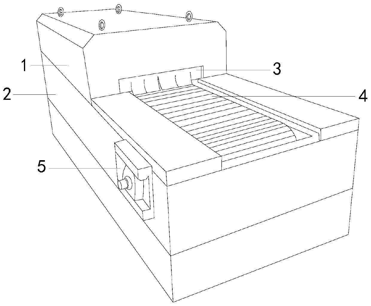
[0020] see figure 1 , the present invention provides a cleaning device for gear processing. Its structure includes: a cleaning mechanism 1, a base 2, a dustproof plate 3, a water absorption mechanism 4, and a driver 5. The cleaning mechanism 1 is connected to the water absorption mechanism 4 and is equipped with On the base 2, the side plate of the base 2 is provided with a driver 5, and the dustproof plate 3 is arranged on the upper part of the middle of the connection between the cleaning mechanism 1 and the water absorption mechanism 4 on the base 2. When the driver 5 is powered on, the internal power mechanism will Drive the cleaning mechanism 1 and the water absorption mechanism 4 to run.

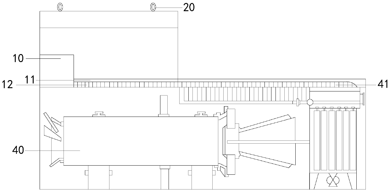
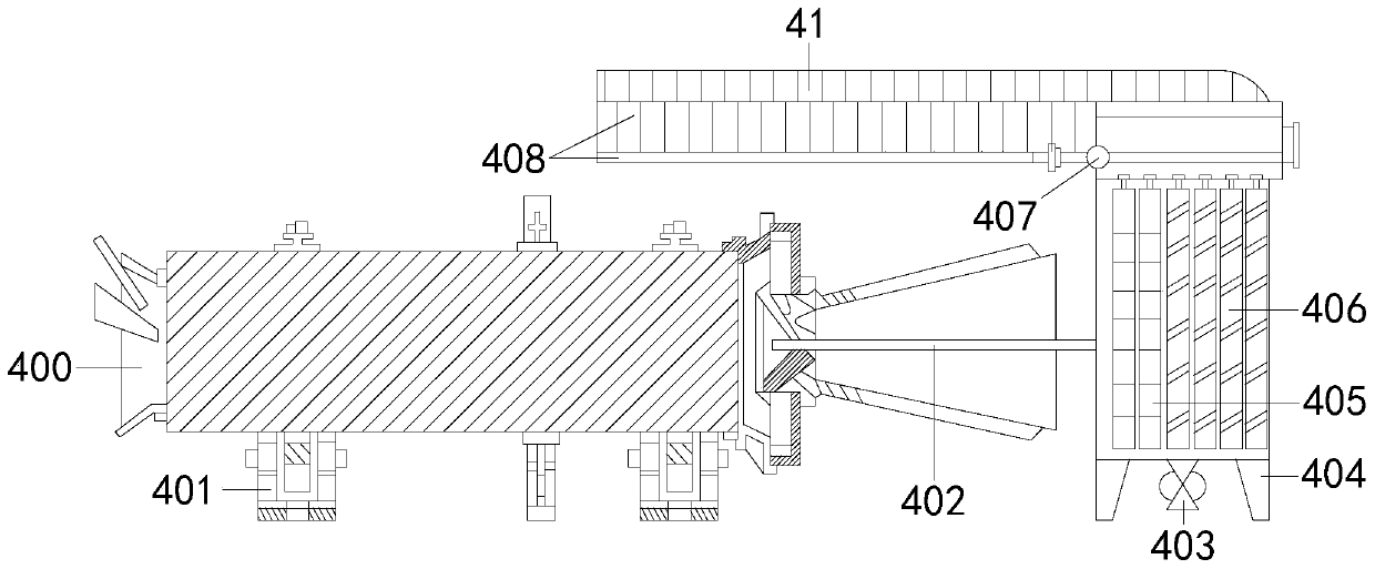
[0021] see figure 2 , Figure 5 , the present invention provides a cleaning device for gear processing, its structure includes: the cleaning mechanism 1 is composed of a water tank 10, a spray pipe 11, and a transmission shaft 12, the water tank 10 is connected to the spray pipe 11...


PUM


Abstract

The invention discloses a cleaning device for gear machining. The cleaning device structurally comprises a cleaning mechanism, a base, a dustproof plate, a water absorption mechanism and a driver. Thecleaning device has the beneficial effects that the cleaning mechanism and the water absorption mechanism which are different from conventional cleaning structures are matched, the cleaning mechanismis firstly used for washing clean residual cleaning fluid components of conventional cleaning, then residual water drops and water stains on the surface of the gear are evaporated by utilizing a unique low-temperature water absorption mode of the water absorption mechanism, the water stains on the surface of the gear are effectively removed by utilizing two different convection gas, and the influence of the water stains after a cleaning liquid on the surface of the gear is removed on the later-stage assembly machining of the gear is avoided.

Description

technical field [0001] The invention relates to the field of gear equipment, in particular to a cleaning device for gear processing. Background technique [0002] With the development of the machinery manufacturing industry, higher and higher requirements are put forward for the processing and assembly precision of gears, and because the gears will be affected by impurities such as oil, dust, and debris during the production and processing process, the gear Cleanliness is also an indicator that must be considered during gear processing. The existing gear cleaning machines generally use an aqueous solution containing cleaning agent to spray the cleaning system to clean the gears, and then rinse them with an aqueous solution containing an antirust agent, and finally clean the gears. The workpiece is blown dry, because the gear workpiece will enter the furnace for carburization in a short time after cleaning, so if the cleaning agent is not mixed with water according to the rat...

Claims


Application Information

Patent Timeline
Patent Type & Authority Applications(China)
IPC IPC(8): B08B3/02F26B5/16F26B21/00F26B21/08
CPCB08B3/022F26B5/16F26B21/004F26B21/086
Inventor 田锦海
Owner 田锦海
Features
  • R&D
  • Intellectual Property
  • Life Sciences
  • Materials
  • Tech Scout
  • Unparalleled Data Quality
  • Higher Quality Content
  • 60% Fewer Hallucinations
Learn More