Plastic bag folding and rubber band binding all-in-one machine

A plastic bag and all-in-one machine technology, which is applied to the parts and packaging of strapping machinery, can solve the problems of irregularity, slow falling speed, deformation, etc.

Inactive Publication Date: 2019-09-03
王秀来
View PDF8 Cites 5 Cited by
  • Summary
  • Abstract
  • Description
  • Claims
  • Application Information

AI Technical Summary

Problems solved by technology

Its existing problems are: First, the handles of the plastic bags are irregular. When the middle part of a stack of plastic bags is pressed by the flashboard on the folding bracket and moves downward, the plastic bags on both sides of the flashboard will The bag part is not symmetrical, and its friction and resistance are different. The front part of the insert board is irregular because of the existence of two handles, and the two handles are even more irregular after the handles are folded. As a rule, when the handle part passes through the folding nip roller, the frictional force generated will inevitably be large, and the descending speed will inevitably be slow, while the part on the other side of the insert (the tail of the plastic bag) is relatively regular, and some are shorter. The plastic bag does not need to be folded at the tail. In this case, the plastic bag on the front side of the board has been folded into three layers, while the tail of the rear side has only one layer. In this way, the rear part of the board is lowered due to low resistance. In this case, the predete

Method used


Image

  • Plastic bag folding and rubber band binding all-in-one machine
  • Plastic bag folding and rubber band binding all-in-one machine
  • Plastic bag folding and rubber band binding all-in-one machine

Examples


Embodiment 1

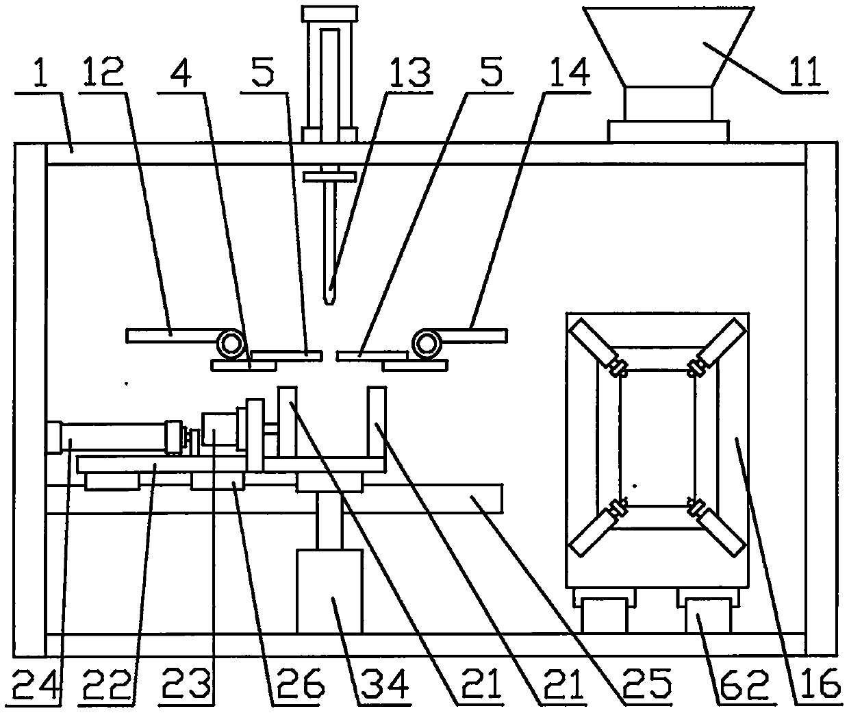
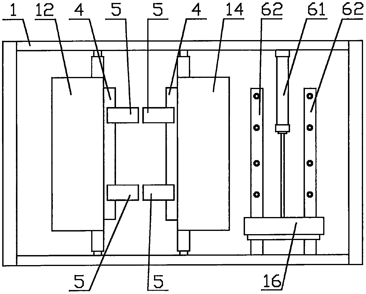
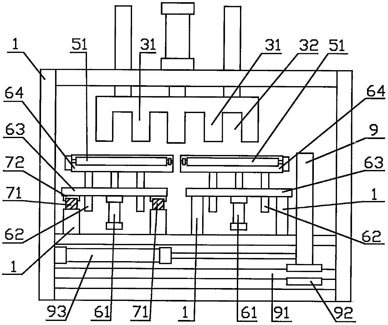
[0063] Embodiment one, such as Figure 1 to Figure 3 As shown: the handle folding device 2 includes a front corner folding mechanism, a trapezoidal front folding plate 21, and a pressure bag hook, and the tail folding device 4 is a rear folding plate 40 and a swing cylinder 41; the described The bag clamping device 5 and the bag holding device 6 include each other, including a splint cylinder 64, a lifting cylinder 61, a guide rod 62, and a beam 63; the bag passing movement device is connected with the bag holding device, that is, the bag passing movement device 7 Connect with the crossbeam 63 of the lifting drive mechanism of the bag holding device 6; the hanging bag clamping mechanism 55 includes two groups of bag clamping devices 5, wherein one group of bag clamping devices 5 is arranged on the frame 1 through the lifting drive mechanism, and the other group The bag clamping device 5 is connected on the bag passing movement device 7 through a lifting drive mechanism, and mo...

Embodiment 2

[0066] Embodiment two, such as Figure 11 to Figure 15 As shown, the difference between Embodiment 2 and Embodiment 1 is that two groups of bag clamping devices 5 are provided, one group of bag clamping devices 5 is connected to the bag passing movement device 7, and can follow the bag passing movement device. Movement, that is, the bag passing movement device 7 is connected with the bag clamping device 5; another group of bag clamping devices 5 is arranged on the frame 1 through the guide rod cylinder 59. The bag holding bar is a horizontal bar 60 arranged left and right;

[0067] like Figure 11 Shown: Install a guide rail 58 again on the rear portion of the guide rail 71, one side of the two splints 50 is slidably installed on the guide rail 58 through the slide block 57 respectively, and a clamping cylinder 56 is respectively installed at the front and rear ends of the guide rail 58 , the cylinder rods of the clamping cylinder 56 are respectively connected on the splint ...

Embodiment 3

[0069] Embodiment 3, the main difference between embodiment 3 and embodiment 1 is: firstly, the described bag clamping device is a kind of finger cylinder 52, and the bag holding rod of the described bag holding device 6 is a kind of interval setting The vertical rod 60; second, the handle folding device is a handbag folding mechanism composed of a bag holding board, a handle folding guide part, a left push plate, a right push plate, etc., please refer to the authorized publication number The utility model patent of CN208361536U is concretely implemented.

[0070] like Figure 16 , 17 Shown: 4 bag-holding rods 60 are set, so that the lower ends of the 4 bag-holding rods 60 are installed on a crossbeam 63 at intervals, above the crossbeam 63, the gap between the two bag-holding rods 60 on the left is forward Two slide blocks 72 are respectively installed front and back on the corresponding frame positions, two guide rails 71 are slidably installed on the slide block 72, and a...


PUM


Abstract

The invention discloses a plastic bag folding and rubber band binding all-in-one machine. The machine comprises a machine frame, a vibration disc device, a rubber band expanding device, a handle folding device, a tail folding device and a plate inserting device, and is characterized in that a bag supporting device, a bag clamping device and a bag conveying movement device are further arranged at the corresponding positions of the inserting plate; the machine further comprises a bundling movement device and a suspension outer bag clamping mechanism, the bag supporting device and the bag clamping device are used for folding a plastic bag from the middle position and clamping and shaping the plastic bag, then the bag clamping device or a bag clamping mechanical arm clamps one side of the plastic bag, and the other side of the plastic bag is inserted into the rubber band expanding device to be bundled. The machine has the advantages that operation from folding to bundling is carried out almost in a clamping plate mechanism of the bag clamping device, so that folding and bundling are integrated without mechanical arm changing, the folding and bundling work is stable and reliable, and the structure is simple and compact.

Description

technical field [0001] The invention relates to a plastic bag folding and rubber band binding integrated machine, specifically a folding and binding integrated device that firstly automatically folds plastic bags, and then uses ring rubber bands to bind the folded plastic bags . Background technique [0002] The plastic bag of the present invention is a plastic convenient bag with two handles, also known as a vest bag. The plastic bags automatically produced by a bag making machine are generally dozens of plastic bags in a neat package. Put them together, and then transport them out one by one intermittently. In order to facilitate storage, sales and use, these plastics need to be folded many times, and finally folded into long strips, and then tied with a ring-shaped rubber band in the middle of the strip-shaped plastic bag, that is, put it in the middle of the plastic bag. A looped rubber band. Then you can enter the market. [0003] For automatic folding devices for p...

Claims


Application Information

Patent Timeline
IPC IPC(8): B65B63/04B65B13/18
CPCB65B13/18B65B63/04
Inventor 王秀来
Owner 王秀来
Why Eureka
Try Eureka