An automatic yarn unloading machine

An automatic, one-stop technology, applied in thin material processing, processing textile material carriers, transporting filamentous materials, etc., can solve the problems of low reliability and low degree of automation, and achieve high reliability, high degree of automation, and improved The effect of positioning accuracy

Active Publication Date: 2021-12-28
WUHAN TEXTILE UNIV
View PDF6 Cites 0 Cited by
  • Summary
  • Abstract
  • Description
  • Claims
  • Application Information

AI Technical Summary

Problems solved by technology

[0004] The purpose of the present invention is to overcome the defects and problems of low degree of automation and low reliability in the prior art, and provide an automatic yarn unloading machine with high degree of automation and high reliability

Method used


Image

  • An automatic yarn unloading machine
  • An automatic yarn unloading machine
  • An automatic yarn unloading machine

Examples


Embodiment 1

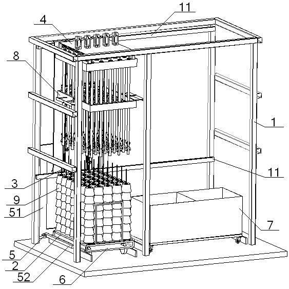
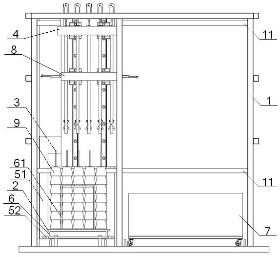
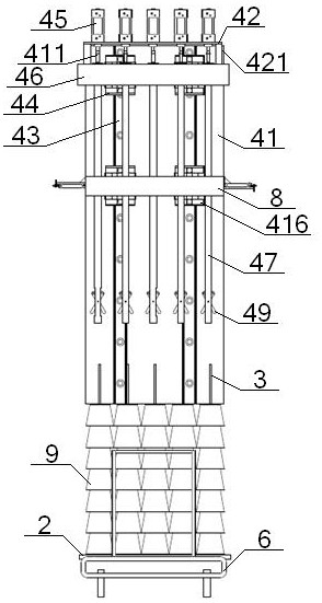
[0054] see Figure 1 to Figure 6, an automatic yarn unloading machine, comprising a frame 1 and a bobbin frame arranged on it, the bobbin frame including a carrier plate 2 and a plurality of bobbins 3 arranged vertically on it, the frame A yarn hanging mechanism 4 is provided at the position above the yarn bobbin stringer 3 on the 1, and the yarn hanging mechanism 4 includes a No. 1 mounting plate 41 and a No. 2 mounting plate 42 perpendicular to each other. There are two No. 1 guide rails 43, a No. 1 slide block 44 is arranged on the No. 1 guide rail 43, a plurality of No. 1 cylinders 45 are arranged on the No. 2 mounting plate 42, and a plurality of No. 1 cylinders 45 are arranged on the No. 2 mounting plate 42. The moving plate 46 is connected to the No. 2 mounting plate 42 through the pillar 421, and the moving plate 46 is connected to the No. 1 slide block 44. There are many sleeve rods 47 vertically set on the moving plate 46, and the sleeve rods 47 and Yarn bobbin stri...

Embodiment 2

[0056] Basic content is the same as embodiment 1, the difference is:

[0057] see Figure 5 , Figure 7 , the end of the sleeve rod 47 close to the yarn bobbin rod 3 is fitted with a bell mouth 410, the small diameter end of the bell mouth 410 is located in the sleeve rod 47, and the outer wall of the large diameter end of the bell mouth 410 is threaded with the inner wall of the sleeve rod 47 end. connect.

Embodiment 3

[0059] Basic content is the same as embodiment 1, the difference is:

[0060] see image 3 , Figure 4 , Figure 5 , Figure 8 , between the No. 2 mounting plate 42 and the moving plate 46, a cylinder connector 411 is provided, and the cylinder connector 411 includes a No. 3 mounting plate 412. The middle part of the upper end of the No. 3 mounting plate 412 is vertically connected with a No. 1 connecting rod 413, the No. 1 connecting rod 413 is connected with the No. 1 cylinder 45, and the lower end of the No. 3 mounting plate 412 is evenly and vertically connected with a plurality of No. 2 connecting rods 414, and the No. 2 connecting rod 414 is threadedly connected with the push rod 48; Sleeve rod 47 comprises rod body 471 and No. 4 mounting plate 472, and one end of described rod body 471 is vertically connected with No. After passing through the moving plate 46, align the yarn bobbin rod 3, and the middle part of the No. 4 mounting plate 472 is provided with a through...


PUM


Abstract

An automatic yarn unloading machine, comprising a frame and a yarn bobbin holder arranged on it, the yarn bobbin holder includes a yarn loading plate and a plurality of yarn bobbin stringing rods vertically arranged on it, and the yarn bobbin stringing rods on the frame are located above There is a yarn hanging mechanism at the position, and the yarn hanging mechanism includes No. 1 mounting plate and No. 2 mounting plate. No. 1 guide rail is set on the No. There is a moving plate connected to it at the bottom, and the moving plate is connected with the No. A push rod is set inside the rod, and a four-link fork is arranged at the lower part of the rod. The middle part of the fork is connected with the rod through a pin. Hinged with each other, the end of the sleeve rod close to the string rod of the yarn tube is sleeved with a bell mouth. This design not only has a high degree of automation, but also has high reliability.

Description

technical field [0001] The invention relates to the technical field of textiles, in particular to an automatic yarn unloading machine, which is mainly suitable for improving the automation degree and reliability of the yarn unloading machine. Background technique [0002] At present, most cheese dyeing enterprises are labor-intensive, and each process requires a lot of labor. With the continuous development of automation technology, people have developed various automatic auxiliary equipment for each process of cheese dyeing. In the bobbin link, in order to quickly unload the yarn, various yarn unloading machines have been developed, but the existing yarn unloading machines often have the following defects: the degree of automation is not high, a lot of human resources are wasted, and the work efficiency is low; The medium stability is low, and it is easy to cause deformation of the workpiece. [0003] Chinese patent, the application publication number is CN107366112A, and ...

Claims


Application Information

Patent Timeline
Patent Type & Authority Patents(China)
IPC IPC(8): D06B23/04B65H67/00
CPCD06B23/04B65H67/00
Inventor 张成俊李冬冬吴晓左小艳刘念戴建雄刘雅昆
Owner WUHAN TEXTILE UNIV
Why Eureka
Try Eureka