Push-pull type grouting system for tunnel lining trolley

A technology for lining a trolley and a grouting system, which is applied to tunnel lining, tunnel, wellbore lining, etc., can solve the problems of stuck grouting hole, deformation of grouting hole, low construction efficiency, etc.

Pending Publication Date: 2019-09-03
PINGDINGSHAN COAL MINE MACHINERY EQUIP CO LTD
View PDF0 Cites 1 Cited by
  • Summary
  • Abstract
  • Description
  • Claims
  • Application Information

AI Technical Summary

Problems solved by technology

[0005] In order to solve the problem that the grouting hole structure of the traditional lining trolley is generally opened and closed manually, the labor intensity of the workers is high and the construction efficiency is low. Moreover, after the grouting is completed, the grouting hole must be cleaned in time, otherwise the residual concrete will easily cause The grouting hole is stuck. At this time, if the grouting hole is forcibly opened and closed by hammering or other methods, it will easily cause the deformation of the grouting hole, and even cause technical problems such as damage to the surface of the poured concrete. The invention provides a tunnel The push-pull grouting system for the lining trolley achieves ingenious design, simple structure, convenience and practicality, improves the opening and closing efficiency of the grouting hole of the lining trolley, overcomes the easy blockage of the traditional grouting pipe, and prevents damage to the existing concrete lining surface. The purpose of improving the grouting effect and improving the quality of tunnel lining construction

Method used


Image

  • Push-pull type grouting system for tunnel lining trolley
  • Push-pull type grouting system for tunnel lining trolley
  • Push-pull type grouting system for tunnel lining trolley

Examples


Embodiment Construction

[0022] The specific implementation manners of the present invention will be further described in detail below in conjunction with the accompanying drawings.

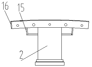
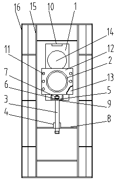
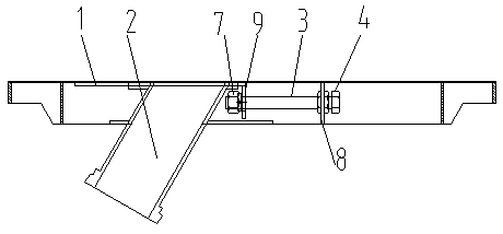
[0023] As shown in the figure, the push-pull grouting system for the tunnel lining trolley includes the vault formwork of the lining trolley and the push-pull grouting mechanism and locking mechanism welded on the vault formwork of the lining trolley. The grouting mechanism includes an opening and closing sliding plate 1, a grouting pipe 2, a pressure plate 12 and a backing plate 13. The grouting pipe 2 is welded on the pressing plate 12, and the middle part of the opening and closing sliding plate 1 is provided with a hole with the same hole diameter as the grouting pipe 2. Grouting holes 14; the backing plate 13 is laid between the pressure plate 12 and the vault formwork of the lining trolley, forming a sliding channel for the front and rear movement of the opening and closing sliding plate 1, and the locking mechanism...


PUM


Abstract

The invention relates to a push-pull type grouting system for a tunnel lining trolley. The push-pull type grouting system comprises a lining trolley vault mold plate, a push-pull type grouting mechanism and a locking mechanism, the push-pull type grouting mechanism and the locking mechanism are welded on the lining trolley vault mold plate, the push-pull type grouting mechanism comprises an opening and closing sliding plate, a grouting pipe, a pressing plate and a backing plate, and a grouting hole the same as the grouting pipe in hole diameter is formed in the middle portion of the opening and closing sliding plate; the backing plate is paved between the pressing plate and the lining trolley vault mold plate, a sliding channel used for moving the opening and closing sliding plate front and back is formed, the locking mechanism is located at the rear end of the opening and closing sliding plate, different positions of coincidence of the grouting hole in the opening and closing slidingplate and the grouting pipe are locked through the locking mechanism, and opening and closing of the grouting system are achieved. The push-pull type grouting system is convenient and practical, improves the opening and closing efficiency of the grouting hole of the lining trolley, overcomes the problem that a traditional grouting pipe is prone to being blocked, eliminates damage to an existing concrete lining surface, improves the grouting effect, improves the tunnel lining construction quality and has good market prospects and development space as for an existing technology.

Description

technical field [0001] The invention relates to the technical field of tunnel lining construction equipment, in particular to a push-pull grouting system for a tunnel lining trolley. Background technique [0002] The grouting hole mechanism is an indispensable component that must be loaded during the grouting construction of the tunnel lining trolley, and is an important structure that affects the efficiency and quality of tunnel construction. [0003] At present, the grouting hole structure of traditional lining trolleys is generally opened and closed manually, which has high labor intensity for workers and low construction efficiency. Moreover, after the grouting is completed, the cleaning of the grouting hole must be carried out in time, otherwise the residual concrete will easily cause the grouting hole to be stuck. Deformation, in severe cases, may even cause damage to the surface of the poured concrete. [0004] How to design an ingenious design, simple structure, co...

Claims


Application Information

Patent Timeline
Patent Type & Authority Applications(China)
IPC IPC(8): E21D11/10
CPCE21D11/102E21D11/105
Inventor 王松喻致蓉王君烨王秀全戚霞夏宾王芬常园园
Owner PINGDINGSHAN COAL MINE MACHINERY EQUIP CO LTD
Why Eureka
Try Eureka