
Vortex thickness measuring method

A thickness measurement and eddy current technology, which is applied to eddy current thickness measurement. For the product field with uniform holes on the circumference of the measurement point, it can solve the problems of unreliability and abnormal measurement values, and achieve rapid measurement, reliable results, and operation. logically simple effect

Active Publication Date: 2019-09-03
无锡市振华开祥科技有限公司
View PDF5 Cites 0 Cited by
  • Summary
  • Abstract
  • Description
  • Claims
  • Application Information

AI Technical Summary

Problems solved by technology

[0005] The purpose of the present invention is to provide an eddy current thickness measurement method, in view of the above problems, to solve the problem that it is difficult to avoid the hole and the abnormal value is easy to appear when measuring the product with holes and the measured value is unreliable

Method used


Image

  • Vortex thickness measuring method
  • Vortex thickness measuring method
  • Vortex thickness measuring method

Examples


Embodiment Construction

[0018] The technical solutions of the present invention will be clearly and completely described below in conjunction with the accompanying drawings.

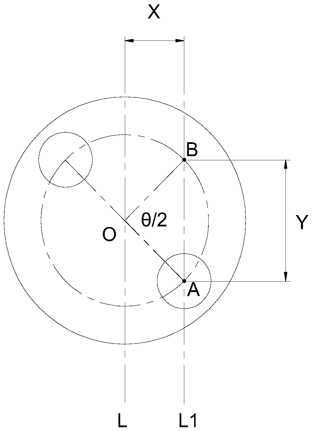
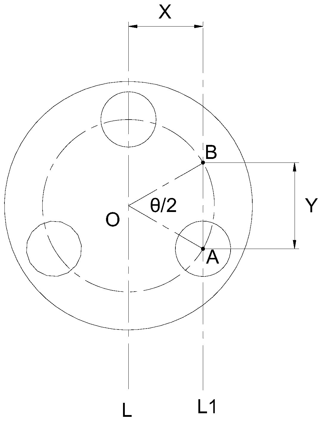
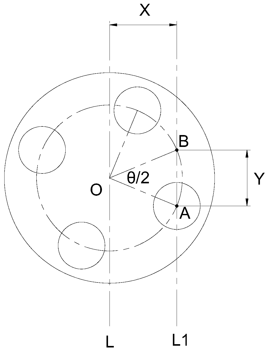
[0019] This embodiment provides an eddy current thickness measurement method, which is mainly aimed at products with uniformly distributed holes. The specific measurement steps are as follows:

[0020] 1) Take one of the hole center positions as the first measurement point A;

[0021] 2) Determine the center O of the circle where the uniformly distributed holes are located and the center angle θ of the two adjacent holes;

[0022] 3) Rotate the first measurement point A around the center O angle to obtain the second measurement point B;

[0023] 4) Make a central axis L parallel to the line connecting points A and B through the center O of the circle, and obtain the distance X between the line AB and the line L, and obtain the distance Y between points A and B;

[0024] 5) Offset the measurement center axis L by X distance ...


PUM


Abstract

The invention discloses a vortex thickness measuring method comprising the following steps: 1) taking one hole center position as a first measuring point A; 2) determining a central angle theta of thecircle center O of a circle where a uniform distribution hole is located and two adjacent holes; 3) rotating a first measurement point A for an angle around the circle center O to obtain a second measurement point B; 4) passing the circle center O, drawing a central axis L parallel to a connection line of the points A and B to obtain a distance X between the AB connection line and the L line andobtain a distance Y between the point A and the point B; 5) deviating the measured central axis L for the X distance to obtain an axis L1, performing measurement by a measuring head with L1 as the central axis, performing measurement at the point A to obtain a first measurement value, then, moving for the Y distance to reach to the point B to measure to obtain a second measurement value; and 6) taking the minimum value in the first measurement value and the second measurement value as a thickness true value. According to the method, the two measurement points are determined by firstly mappingthe hole position of the product, the relative positions of the two measurement points can ensure that at least one of the two measurement points does not fall into the hole, thus at least one of thetwo measurement values is a true value.

Description

technical field [0001] The invention relates to the technical field of non-destructive testing, in particular to an eddy current thickness measuring method, especially for products with uniformly distributed holes on the circumference of measuring points. Background technique [0002] In the processing of many products, the covering layer on the surface usually has dual functions of protection and decoration for the covered substrate, such as coating, and the thickness of the coating is also an important technical indicator. If the thickness is too thin, it will be difficult to perform its function. If the thickness is too thick, it will cause waste of materials, and if the thickness is uneven or does not meet the specified requirements, it will cause other adverse effects. [0003] At present, the eddy current coating thickness gauge is used to detect its thickness. Its working principle is that when the probe is in contact with the sample to be tested, the high-frequency e...

Claims


Application Information

Patent Timeline
IPC IPC(8): G01B7/06
CPCG01B7/105
Inventor 孙黎明
Owner 无锡市振华开祥科技有限公司
Learn More