Cleaning equipment for automobile part production

A technology for cleaning equipment and spare parts, which is applied to cleaning methods using tools, cleaning methods using liquids, lighting and heating equipment, etc., which can solve the problems of high labor intensity, unsatisfactory cleaning effect, low cleaning and drying efficiency, etc. question

Inactive Publication Date: 2019-09-06
佘娟
View PDF10 Cites 6 Cited by
  • Summary
  • Abstract
  • Description
  • Claims
  • Application Information

AI Technical Summary

Problems solved by technology

[0002] At present, in the process of automobile processing and assembly, oil stains and residual sand often adhere to the outer surface and inner cavity surface of the parts used for assembly. Therefore, cleaning and drying are usually required after the parts are processed to avoid residual sand, Pollutants such as oil stains affect the quality of parts. In the existing auto parts cleaning and drying process, manual cleaning is usually used to clean the residual sand and oil stains on the surface of the parts, and then they are dried manually. The way of drying is not only labor-intensive, the efficiency of cleaning and drying is low, but also the cleaning effect is not ideal. Therefore, we propose a cleaning equipment for the production of auto parts in order to solve the above-mentioned problems

Method used


Image

  • Cleaning equipment for automobile part production
  • Cleaning equipment for automobile part production
  • Cleaning equipment for automobile part production

Examples


Embodiment Construction

[0026] The technical solutions of the present invention will be further described below in conjunction with the accompanying drawings and through specific implementation methods.

[0027] Wherein, the accompanying drawings are only for illustrative purposes, showing only schematic diagrams, rather than physical drawings, and should not be construed as limitations on this patent; in order to better illustrate the embodiments of the present invention, some parts of the accompanying drawings will be omitted, Enlargement or reduction does not represent the size of the actual product; for those skilled in the art, it is understandable that certain known structures and their descriptions in the drawings may be omitted.

[0028] In the drawings of the embodiments of the present invention, the same or similar symbols correspond to the same or similar components; , "inner", "outer" and other indicated orientations or positional relationships are based on the orientations or positional ...


PUM


Abstract

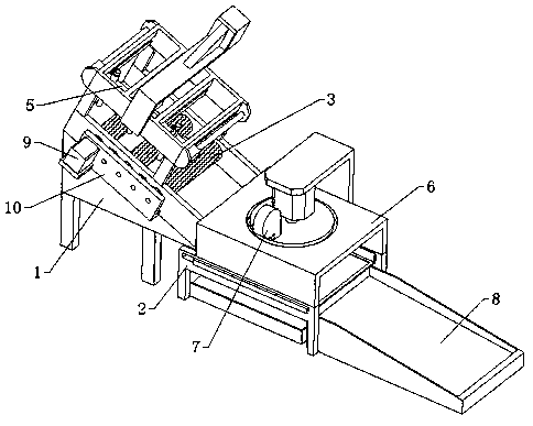
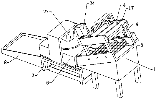
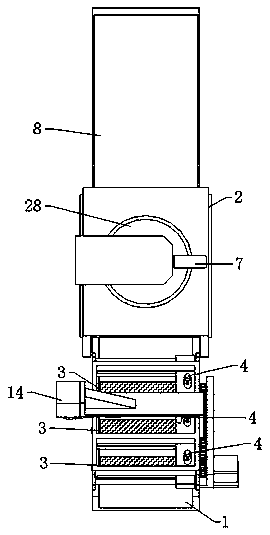
The invention relates to the field of cleaning equipment, in particular to the cleaning equipment for automobile part production. The cleaning equipment comprises a cleaning table, a drying table, a cleaning mechanism and a drying mechanism, wherein the cleaning mechanism is arranged on the cleaning table; the upper surface of the cleaning table is obliquely arranged; the cleaning mechanism comprises a cleaning wheel assembly and a flushing assembly; the cleaning wheel assembly comprises three roller shafts arranged in the linear direction of the cleaning table and the three roller shafts canbe rotatably arranged on the cleaning table; the flushing assembly comprises three cleaning punches and a horizontal moving plate, and the three cleaning punches are arranged on the horizontal movingplate respectively; the drying mechanism comprises a drying bin and a hot gas fan, the drying bin is fixedly arranged at the top of the drying table, and the hot gas fan is arranged above the drying bin; one end, away from the cleaning table, of the drying table is provided with a storage rack; and one end of the storage rack is in butt joint with one end of the drying table. With the cleaning equipment, automobile parts can be automatically cleaned and dried, and the cleaning and drying efficiency is improved.

Description

technical field [0001] The invention relates to the field of cleaning equipment, in particular to a cleaning equipment used for the production of auto parts. Background technique [0002] At present, in the process of automobile processing and assembly, oil stains and residual sand often adhere to the outer surface and inner cavity surface of the parts used for assembly. Therefore, cleaning and drying are usually required after the parts are processed to avoid residual sand, Pollutants such as oil stains affect the quality of parts. In the existing auto parts cleaning and drying process, manual cleaning is usually used to clean the residual sand and oil stains on the surface of the parts, and then they are dried manually. The way of drying is not only labor-intensive, the efficiency of cleaning and drying is low, but also the cleaning effect is not ideal. Therefore, we propose a cleaning equipment for the production of auto parts in order to solve the above-mentioned problem...

Claims


Application Information

Patent Timeline
Patent Type & Authority Applications(China)
IPC IPC(8): B08B3/02B08B1/00B08B1/04B08B13/00F26B15/14F26B21/00F26B25/18
CPCB08B1/002B08B1/04B08B3/02B08B13/00F26B15/14F26B21/004F26B25/18
Inventor 佘娟刘会军
Owner 佘娟
Why Eureka
Try Eureka