Thin wood chip processing device

A processing device and a technology for veneer chips, which are used in the manufacture of veneer chips, wood processing appliances, manufacturing tools, etc., can solve problems such as wood waste and increase labor costs, and achieve convenient operation, high production utilization rate and high quality. Effect

Active Publication Date: 2019-09-06
惠安县益汇聚科技发展有限公司
View PDF8 Cites 0 Cited by
  • Summary
  • Abstract
  • Description
  • Claims
  • Application Information

AI Technical Summary

Problems solved by technology

[0002] In the prior art, the processing process of the veneer is to first obtain equal sections of wood through a cutting device, put it into the friction rollers arranged symmetrically front and back for surface treatment, and then make the veneer under the action of a cutter, and then In this process, the cutting device for making equal lengths of wood is separated from the device for making thin wood chips. It requires manpower to transport the wood and push the wood on the cutting equipment to cut it, and then put the equal lengths of wood into the chip making device by manpower In this process, the cooperation between the devices requires a large amount of manpower to assist and participate, increasing its manpower cost
[0003] Secondly, for the existing sheet-making device, the outer surface of the wood is processed by the rotation of the relative friction wheels, and when continuous thin wood chips are made by the cutter, the falling process of the wood passes through the rotation of the relative friction wheels. Rotate and press down so that the wood is cut into thin wood chips. In this way, the descending height of the wood is related to the diameter of the friction wheel, and for the processing of slightly thinner wood thin wood chips, the remaining wood that cannot be chipped is large. waste of wood

Method used


Image

  • Thin wood chip processing device
  • Thin wood chip processing device
  • Thin wood chip processing device

Examples


Embodiment Construction

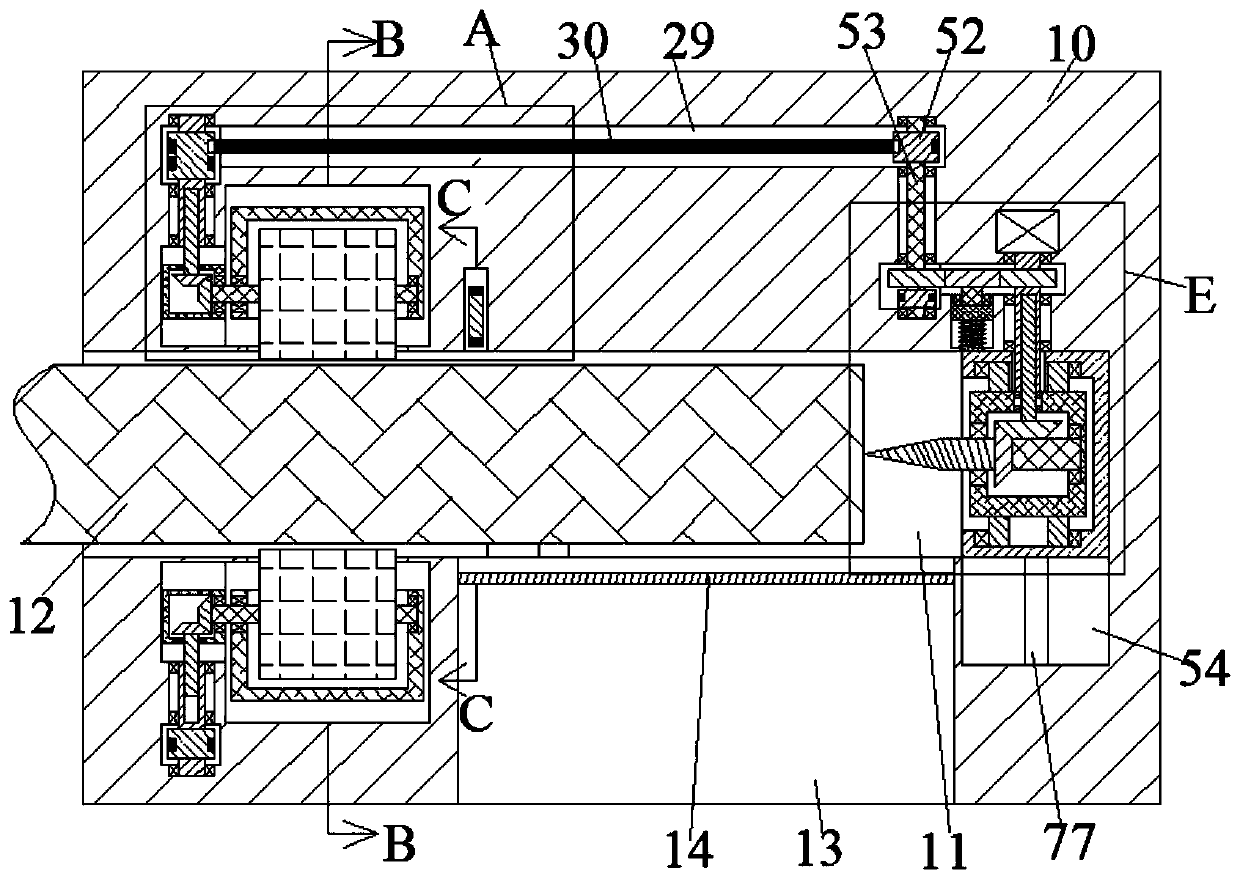
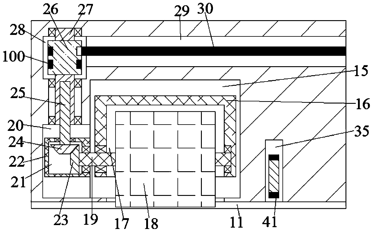
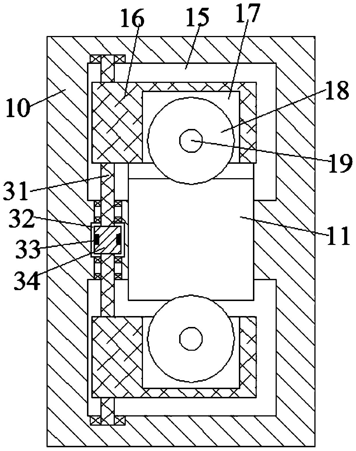
[0021] Combine below Figure 1-8 The present invention is described in detail, and for convenience of description, the orientations mentioned below are now stipulated as follows: figure 1 The up, down, left, right, front and back directions of the projection relationship itself are the same.

[0022] refer to Figure 1-8, according to an embodiment of the present invention, a veneer processing device includes a machine body 10, the machine body 10 is provided with a conveying chamber 11 facing left after being opened, and the wood 12 to be processed is slidably placed in the conveying chamber 11, so The conveying cavity 11 is symmetrically provided with a peeling device up and down, and the peeling device is used to remove the bark on the surface of the wood 12, and the right side of the peeling device is provided with a cutting device, and the cutting device is used to remove the bark from the wood 12. 12 After the peeling process, cut to the required width of veneer. The l...


PUM


Abstract

The invention discloses a thin wood chip processing device. The thin wood chip processing device comprises a machine body, wherein a conveying cavity with a leftward opening is arranged in the machinebody, the conveying cavity is internally provided with a wood to be treated in a sliding mode, the conveying cavity is vertically and symmetrically provided with peeling devices, the peeling devicesare used for peeling off barks on the surface of the wood, and a cutting device is arranged on the right side of the peeling devices. According to the thin wood chip processing device, the structure is simple, operation is convenient, the wood is subjected to outer surface treatment through the peeling devices, so that prepared thin wood chips are high in quality and the efficiency is high, a chipmaking device works in the process of pushing the wood into the conveying cavity to enable the cut wood to be fixed on the chip making device, the chip making device works to enable the peeled wood to rotate and descend at the same time so as to prepare continuous thin wood chip under the action of a thin chip tool, compared with a traditional machine, the chip making device has the advantages that the chip making utilization rate of wood is high, and the rest of wood core which cannot be made into the thin wood chips directly is driven by a chip-making rotating block to rotate to an externalspace to be taken out, so that the thin wood chip processing device is convenient and efficient.

Description

technical field [0001] The invention relates to the technical field of wood processing, in particular to a veneer processing device. Background technique [0002] In the prior art, the processing process of the veneer is to first obtain equal sections of wood through a cutting device, put it into the friction rollers arranged symmetrically front and back for surface treatment, and then make veneer under the action of a cutter. In this process, the cutting device for making equal lengths of wood is separated from the device for making thin wood chips. It requires manpower to transport the wood and push the wood on the cutting equipment to cut it, and then put the equal lengths of wood into the chip making device by manpower Among them, the cooperation between the devices requires a large amount of manpower to assist and participate, increasing its manpower cost. [0003] Secondly, for the existing sheet-making device, the outer surface of the wood is treated by the rotation ...

Claims


Application Information

Patent Timeline
Patent Type & Authority Applications(China)
IPC IPC(8): B27L5/02
CPCB27L5/02
Inventor 不公告发明人
Owner 惠安县益汇聚科技发展有限公司
Why Eureka
Try Eureka