Multi-column floating wind power generation device

A technology of wind power generation device and wind power generating set, which is applied in wind power generation, installation/supporting configuration of wind power generators, floating buildings, etc., and can solve the problem of Spar-type floating foundation with large draft and unable to contribute to roll and pitch stability. Problems such as low inertia and small moment of inertia on the water plane surface can achieve the effect of reducing the demand for drainage volume, reducing manufacturing costs, and reducing wave loads.

Pending Publication Date: 2019-09-06
SHANGHAI JIAOTONG UNIV
View PDF7 Cites 4 Cited by
  • Summary
  • Abstract
  • Description
  • Claims
  • Application Information

AI Technical Summary

Problems solved by technology

[0003] The shortcomings of the existing technology are: the draft of the Spar type floating foundation is relatively large, generally reaching more than 80m, so it is not suitable for use in relatively shallow sea areas, and its small waterline area results in a relatively small waterline surface inertia moment. Small, unable to contribute to roll and pitch stability
However, the above patents did not take measures to lower the center of gravity, the shape of the water plane surface is complex and the area is large, and the hydrodynamic performance is poor

Method used


Image

  • Multi-column floating wind power generation device
  • Multi-column floating wind power generation device
  • Multi-column floating wind power generation device

Examples


Embodiment Construction

[0047] The present invention will be described in detail below in conjunction with specific embodiments. The following examples will help those skilled in the art to further understand the present invention, but do not limit the present invention in any form. It should be noted that those skilled in the art can make several changes and improvements without departing from the concept of the present invention. These all belong to the protection scope of the present invention.

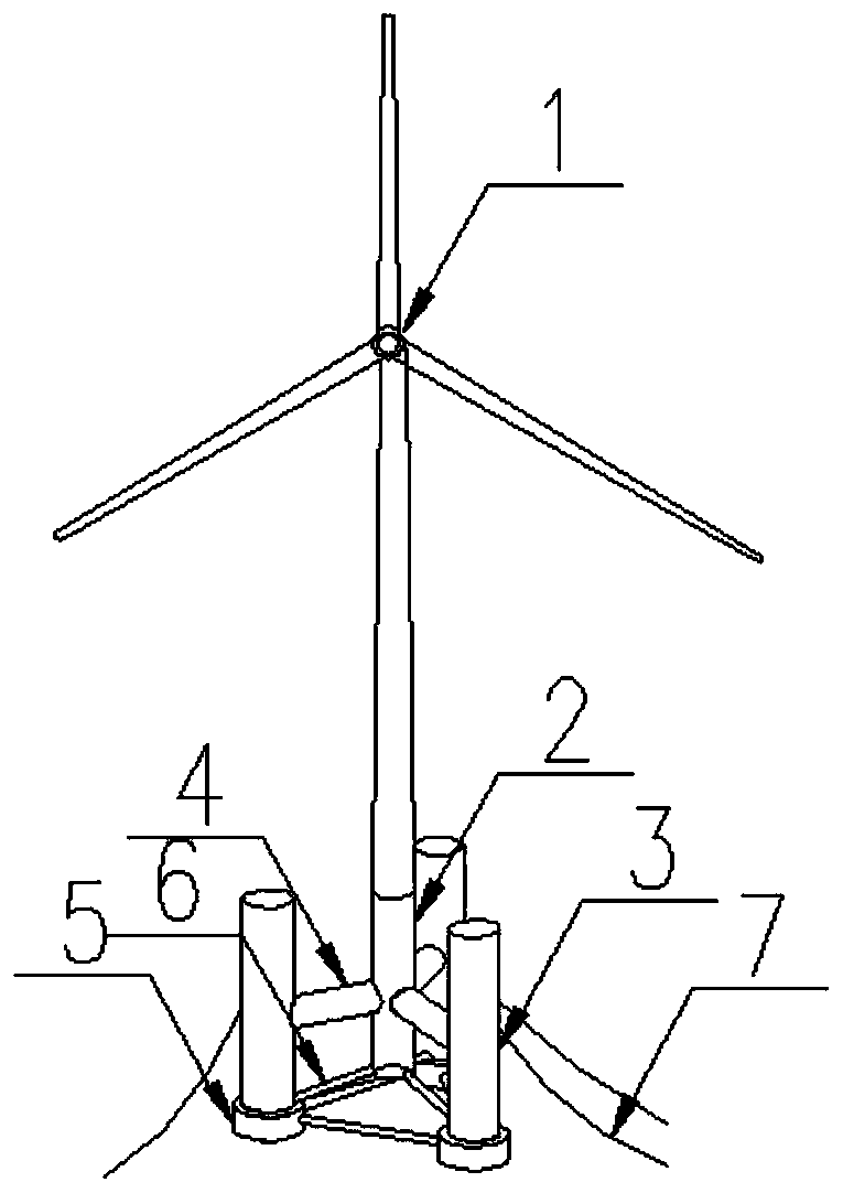
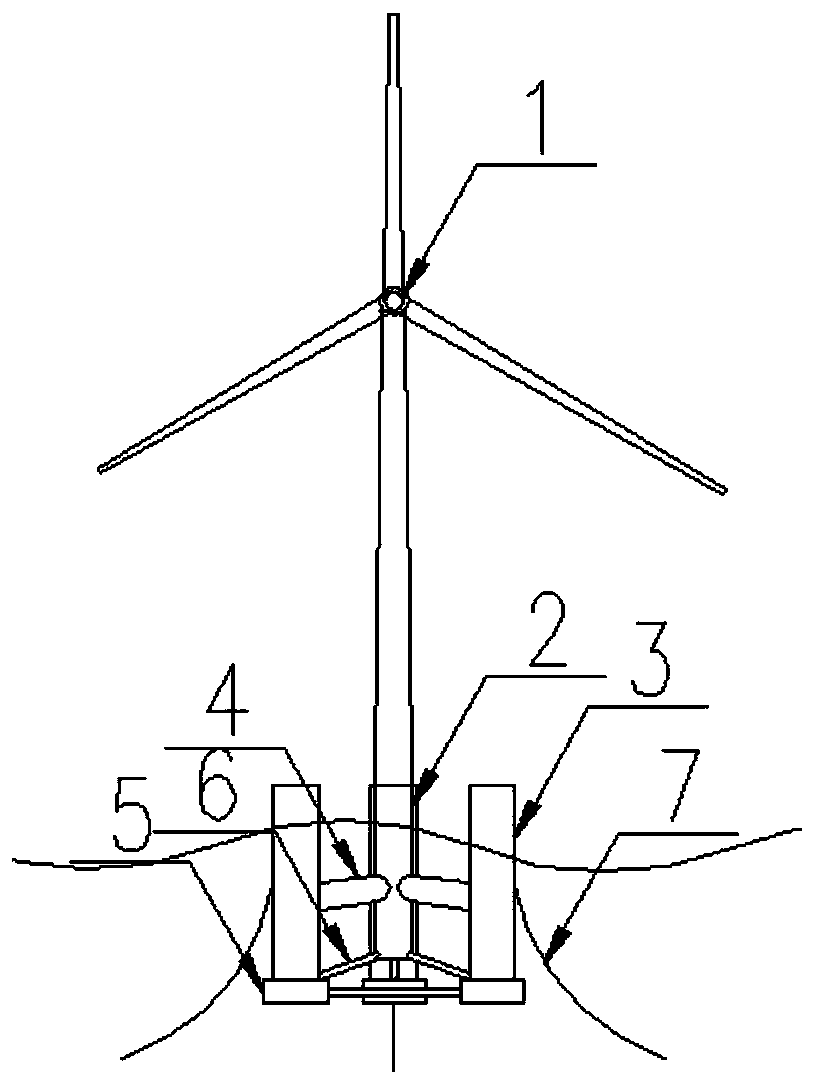
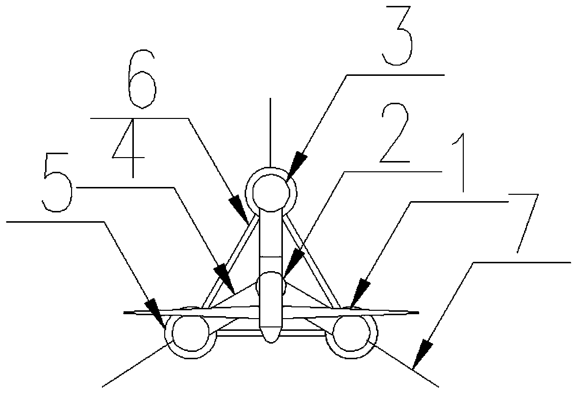
[0048] Such as Figure 1 to Figure 5 As shown, a multi-column floating wind power generation device provided by the present invention includes: a wind power generating unit 1, a central column 2, a side column 3, a cross brace 4, a column shoe 5, a truss structure 6 and a mooring system 7. Among them, the wind power generating set 1 is fixedly arranged on the center column 2, the middle and bottom of the side column 3 are respectively connected with the mooring system 7 and the column shoe 5, and the tw...


PUM


Abstract

The invention provides a multi-column floating wind power generation device. The multi-column floating wind power generation device includes a wind generating set, a column device, a truss component,a transverse brace and a mooring system, wherein the column device is divided into side columns and a central column, and the side columns and the central column are mainly connected by the transversebrace; the wind generating set is arranged on the central column device; the truss component is arranged on the column device, and the column device is connected and supported by the truss component;and the mooring system is connected with the side columns of the column device. According to the multi-column floating wind power generation device, the inclined cylindrical transverse brace locatedbelow the water line surface is adopted to provide certain buoyancy and enable the whole buoyancy center to move up, and the drainage volume demand of the side columns is reduced, and therefore the diameter of the side columns is reduced, and the good hydrodynamic performance is obtained. Column shoes with large diameter are adopted at the lower end of the side columns to act as permanent ballasttanks, so that the multi-column floating wind power generation device has the functions of reducing the overall gravity center to below the buoyancy center and increasing the heaving damping.

Description

technical field [0001] The invention relates to the field of floating foundations, in particular to a multi-column floating wind power generation device. Background technique [0002] At present, the common floating foundations mainly include Spar (single column) type floating foundation, semi-submersible floating foundation and TLP (tension leg) type floating foundation. The technology closest to this patent is Spar type floating foundation and semi-submersible floating foundation. The Spar-type floating foundation is in the shape of a cylinder with a simple structure. The center of gravity is lower than the center of buoyancy through ballasting, and the hydrodynamic performance is better. The semi-submersible floating foundation has columns with large spacing, which can provide a certain restoring moment and has a small draft. [0003] The shortcomings of the existing technology are: the draft of the Spar type floating foundation is relatively large, generally reaching m...

Claims


Application Information

Patent Timeline
Patent Type & Authority Applications(China)
IPC IPC(8): B63B35/44B63B43/04F03D13/25
CPCB63B35/44B63B43/04F03D13/25B63B2035/446Y02E10/727Y02E10/72B63B2001/128B63B2001/126B63B1/125F05B2240/97F05B2240/93B63B21/50B63B2035/442F05B2260/30
Inventor 何炎平吴浩宇赵永生阳杰陈哲刘亚东
Owner SHANGHAI JIAOTONG UNIV
Why Eureka
Try Eureka