Mounting structure and method of high-and-large-space clean room

A technology for tall and large spaces and installation structures, applied in building construction, covering/lining, construction, etc., can solve problems such as long-term and high safety hazards, and achieve the effects of improving safety, improving installation efficiency, and reducing connection gaps

Inactive Publication Date: 2019-09-06
川楚联合国际工程有限公司
View PDF11 Cites 5 Cited by
  • Summary
  • Abstract
  • Description
  • Claims
  • Application Information

AI Technical Summary

Problems solved by technology

[0004] In order to ensure the verticality of the metal wall panels, when installing each metal wall panel, it is necessary to fine-tune the position of the metal wall panels to meet the level and verticality requirements of the installation. Time work, high potential safety hazard

Method used


Image

  • Mounting structure and method of high-and-large-space clean room
  • Mounting structure and method of high-and-large-space clean room
  • Mounting structure and method of high-and-large-space clean room

Examples


Embodiment 1

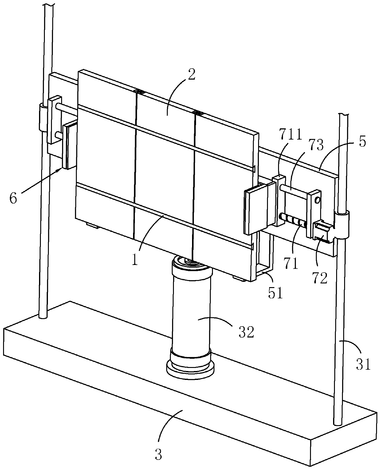
[0043] Such as figure 1 As shown, an installation structure of a clean room in a tall space includes a metal wall plate 2, a fixed rod 1 and a moving seat 3. The moving seat 3 is provided with a lifting plate 5, and the bottom wall of the lifting plate 5 is fixedly provided with two supporting plates. 51, the metal wall plate 2 is placed on the support plate 51. The moving base 3 is provided with a driving source for driving the lifting plate 5 to lift. The moving base 3 is fixedly provided with a column 31 along the vertical direction. Pneumatic cylinder 32, the piston rod of pneumatic cylinder 32 is fixedly connected with lifting plate 5.

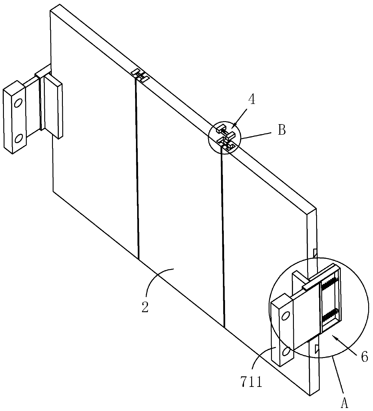
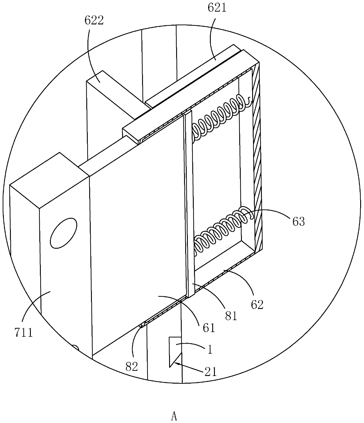
[0044] Such as figure 2 , 3As shown, the side wall of the metal wall panel 2 close to the wall is provided with a card slot 21, the card slot 21 is set as a dovetail groove, and the dovetail groove is arranged along the width direction of the metal wall panel 2, and the fixing rod 1 is clamped on at least two metal walls. In the slot...

Embodiment 2

[0054] An installation method for a clean room in a tall space, comprising the following steps:

[0055] S1. Move the moving seat 3 to the wall where the metal wall panel 2 is to be installed;

[0056] S2. Insert the fixing rod 1 into the slot 21 of the metal wall board 2, and then fix and connect the adjacent metal wall boards 2 through the connector 4, so that multiple metal wall boards 2 are connected side by side as a whole;

[0057] S3. Drive the clamping part 6 to press against the side wall of the metal wall plate 2 through the drive assembly 7, and then drive the lifting plate 5 to move upward through the driving source until the metal wall plate 2 moves to the wall surface to be constructed;

[0058] S4. Fix the metal wall panels 2 on the wall with self-tapping screws, and seal the joints of the adjacent metal wall panels 2 with a sealant.

[0059] A plurality of metal wall panels 2 are fixed as a whole, which is convenient for installation, reduces the time for work...


PUM


Abstract

The invention relates to a mounting structure and method of a high-and-large-space clean room, and belongs to the technical field of mounting of cleanroom metal wall plates. The mounting structure comprises metal wall plates, fixing rods and a moving seat; clamping grooves are formed in the side walls, close to a wall, of the metal wall plates, and the fixing rods are clamped in the clamping grooves of the two or more metal wall plates; every two adjacent metal wall plates are fixedly connected through a connecting piece; a lifting plate is arranged on the moving seat, and clamping parts usedfor being clamped in the side walls of the metal wall plates are slidably arranged at the two ends of the lifting plate in the length direction of the lifting plate; and the lifting plate is providedwith a driving assembly for driving the two clamping parts to move in the direction getting close to or away from each other, and the moving seat is provided with a driving source used for driving thelifting plate to ascend and descend. The multiple metal wall plates are fixed into a whole, thus mounting is convenient, the time of working at the high altitude is reduced, and safety is improved.

Description

technical field [0001] The invention relates to the technical field of installation of metal wall panels in clean rooms, in particular to an installation structure and method for clean rooms with high and large spaces. Background technique [0002] At present, in order to meet the needs of production technology and production scale, industrial clean workshops are gradually developing in the direction of large span and high space. The construction of this type of clean room faces three challenges: safety and stability of the overall structure of the clean enclosure, simple and flexible installation, and aesthetics. difficulties in one aspect. [0003] Due to the needs of industrial production and use functions in clean industrial workshops, the installation height of metal wall panels on walls is often very high. When installing metal wall panels, workers need to work at heights, and multiple metal wall panels need to be installed side by side on the wall of each floor heigh...

Claims


Application Information

Patent Timeline
Patent Type & Authority Applications(China)
IPC IPC(8): E04F13/12E04F21/18
CPCE04F13/12E04F21/1838
Inventor 陈少博孔浩
Owner 川楚联合国际工程有限公司
Why Eureka
Try Eureka