Separation and reunion device

A technology of a clutch device and a mounting plate, which is applied to non-mechanical transmission-operated locks, building locks, buildings, etc., can solve problems such as inconvenience for users, increased maintenance costs, and knob damage, and achieves good anti-theft capability and reliable work. The effect of strong performance and low manufacturing cost

Pending Publication Date: 2019-09-06
NINGBO WANGTONG LOCKS
View PDF0 Cites 5 Cited by
  • Summary
  • Abstract
  • Description
  • Claims
  • Application Information

AI Technical Summary

Problems solved by technology

This kind of structure will cause permanent damage to the knob when it is violently opened, and the function of the lock needs to be replaced again. On the one hand, it will not only cause inconvenience to the user, but also increase the cost of maintenance; on the other hand , this anti-breaking process is not easy to grasp in manufacturing. The

Method used


Image

  • Separation and reunion device
  • Separation and reunion device
  • Separation and reunion device

Examples


Example Embodiment

[0026] The technical solutions of the embodiments of the present invention will be clearly and completely described below with reference to the accompanying drawings. Obviously, the described embodiments are only a part of the embodiments of the present invention, rather than all the embodiments. Based on the embodiments described in the present invention, all other embodiments obtained by those of ordinary skill in the art without creative work are within the protection scope of the present invention.

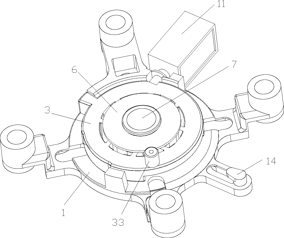
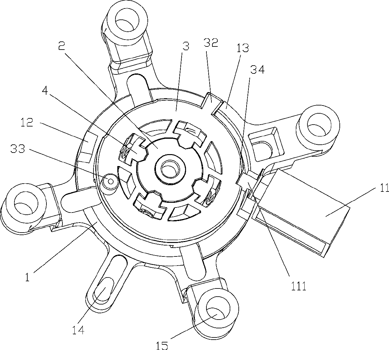
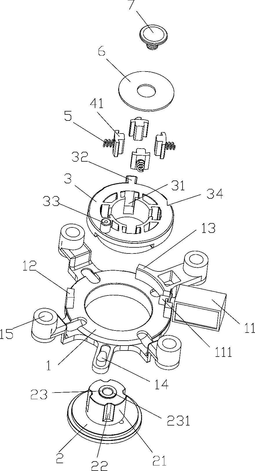
[0027] The embodiment of the present invention provides a clutch device with a simple structure, low manufacturing cost, and strong working reliability. When applied to an electronic lock, it can produce good anti-theft capabilities, and when it is opened violently, it can ensure that the lock will not When opened, it can also protect the internal parts.

[0028] Such as Figure 1 to Figure 9 As shown, a clutch device includes a rotating shaft 21, a turntable 3, and a bracket 1. T...


PUM


Abstract

The invention discloses a separation and reunion device which comprises a rotary shaft, a rotary disc and a bracket, wherein the rotary shaft is inserted in an inner hole in the middle of the rotary disc; a plurality of axial clamping slots are formed in the side wall of the rotary shaft; the inner hole of the rotary disc is provided with limiting fixture blocks, and the number of the limiting fixture blocks is corresponding to that of the clamping slots; the limiting fixture blocks are clamped in the clamping slots to limit mutual rotation between the rotary shaft and the rotary disc; an elastic piece is arranged between the limiting fixture blocks and the inner wall of the rotary disc; the limiting fixture blocks are stressed by external force to compress the elastic piece to separate the limiting fixture blocks from the clamping slots, so that rotation between the rotary shaft and the rotary disc is realized; the bracket is connected with an electromagnetic device; a locking openingis formed in the side wall of the rotary disc; and the electromagnetic device stretches out of the locking rod and inserts the locking rods into the locking opening to lock the rotary disc. The separation and reunion device is simple in structure, low in manufacturing cost and high in working reliability, can generate high anti-theft capacity when being applied to an electronic lock, and can ensure that a lock is not unlocked and also protects internal parts when the lock is unlocked violently.

Description

Technical field [0001] The invention relates to a clutch device. Background technique [0002] At present, electric locks have been widely used in people's lives. They generally include an electronic control module and a mechanical locking device. The electronic control module realizes the locking and unlocking of the electric lock by controlling the action of the locking device. The existing electric lock locking devices are divided into full electric locking devices and semi-electric locking devices. The working processes of the two devices are obviously different. Among them, the full electric locking device is the electronic control module directly driving the locking device to unlock. The semi-electric locking device only uses the electronic control module to release the locking bolt limit mechanism, and then the locking device is driven by the manual door handle to unlock the bolt, thereby unlocking. [0003] Nowadays, the universal electronic lock knobs on the market must e...

Claims


Application Information

Patent Timeline
IPC IPC(8): E05B47/00E05B15/00E05B17/20
CPCE05B15/00E05B17/2084E05B47/0002E05B2047/0026
Inventor 韩文杰王壤
Owner NINGBO WANGTONG LOCKS
Why Eureka
Try Eureka