Eureka AIR delivers breakthrough ideas for toughest innovation challenges, trusted by R&D personnel around the world.

Mechanical vehicle transmission shaft retarder

A transmission shaft and mechanical technology, applied in the field of mechanical vehicle transmission shaft retarder, can solve the problems of increasing transmission system load, energy waste, and maintenance difficulties, so as to ensure stability and reliability, improve safety performance, Guarantee the effect of response speed

Pending Publication Date: 2019-09-06
朱益荣
View PDF1 Cites 0 Cited by
  • Summary
  • Abstract
  • Description
  • Claims
  • Application Information

AI Technical Summary

Problems solved by technology

[0005] The problem with the existing eddy current retarder is that when the eddy current retarder is not working, the rotor part will rotate with the transmission shaft at high speed, which increases the moment of inertia of the transmission shaft and the load of the transmission system. Cause energy waste. If the dynamic balance of the rotor part is unbalanced, it will directly affect the noise and vibration of the vehicle drive train, increase the energy consumption of the vehicle, affect the fuel consumption of fuel vehicles, and affect the cruising range of new energy vehicles. According to statistics, eddy current slow The energy consumption of the rotor part of the gearbox idling with the transmission shaft accounts for about 1-2% of the energy consumption of the car
[0006] In addition, the traditional eddy current retarder and electromagnetic controller have complex structure, high cost and difficult maintenance

Method used


Image

  • Mechanical vehicle transmission shaft retarder
  • Mechanical vehicle transmission shaft retarder
  • Mechanical vehicle transmission shaft retarder

Examples


Embodiment 1

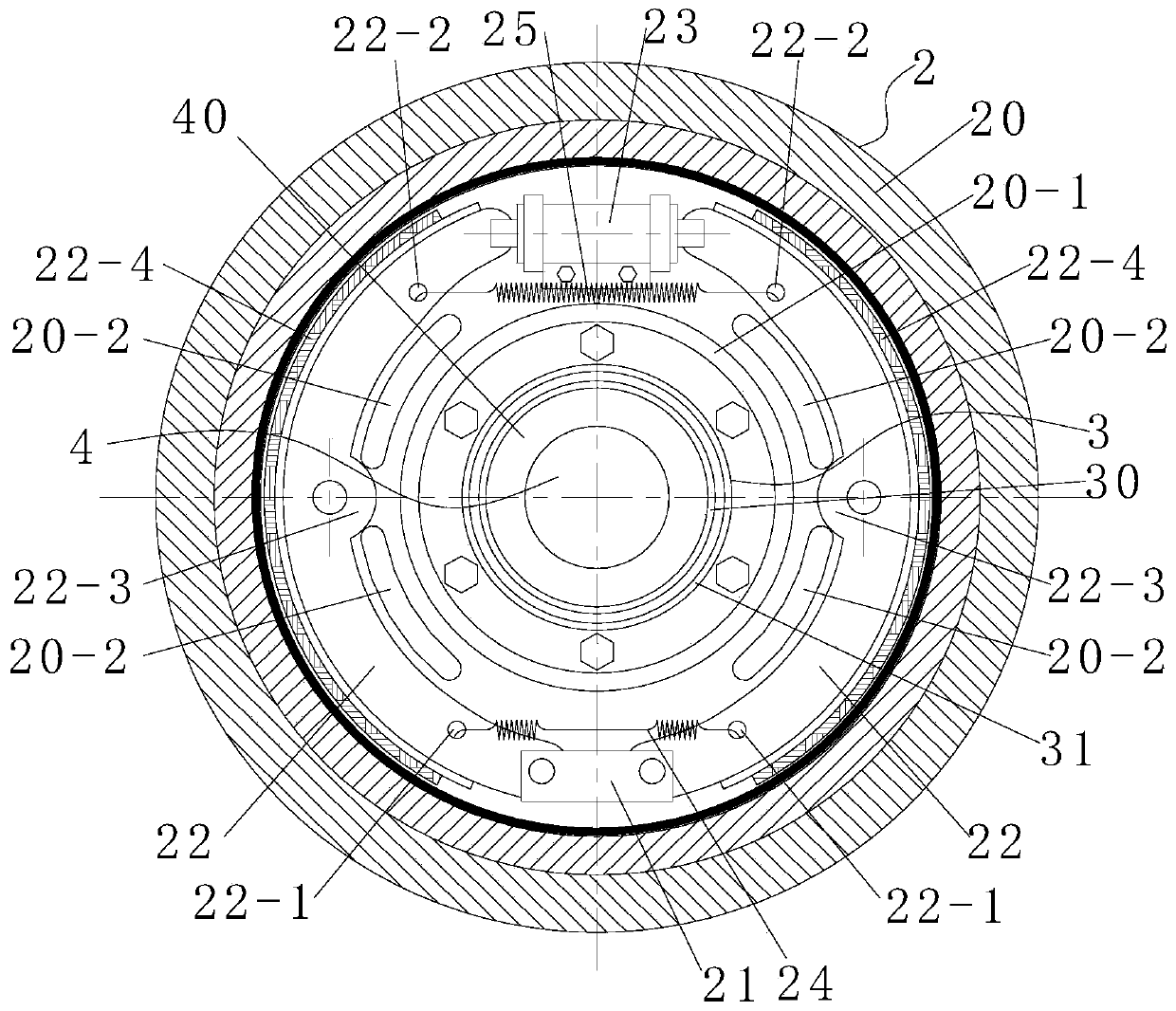
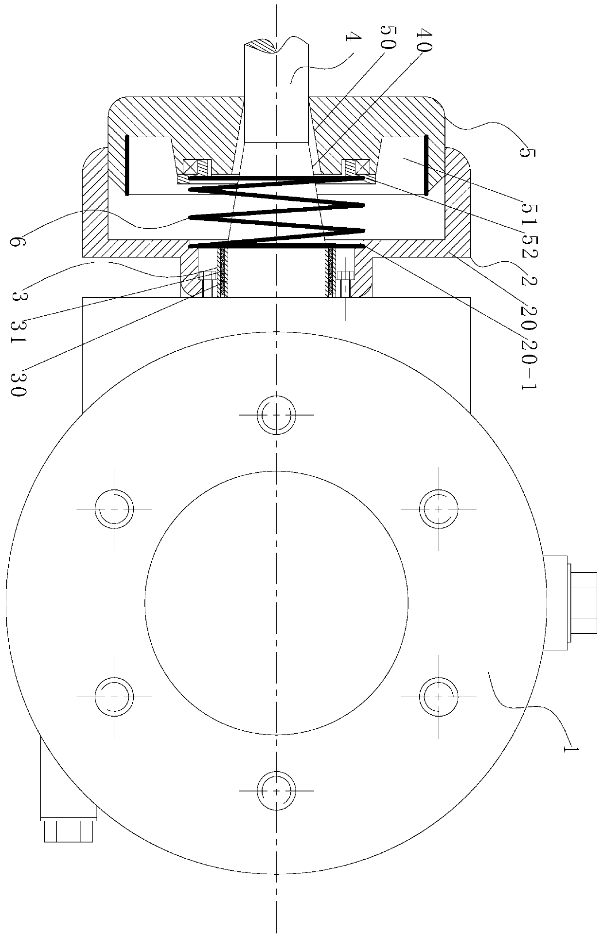
[0043] For the mechanical vehicle transmission shaft retarder, the threshold value written in the controller is set to 80km / h, and the vehicle speed sensor transmits the vehicle speed information to the controller in real time, and the controller compares the transmitted vehicle speed information with the threshold value of 80km / h. When the vehicle speed exceeds 80km / h, the controller controls the electromagnetic relay and the electromagnetic valve to open at the same time. At this time, the spirally wound wire in the electromagnetic tube 3 is energized to generate an electromagnetic field, and the brake wheel cylinder 23 rodless cavity enters oil. Next, the turntable 5 further compresses the compression spring 6 through the spring seat 52, and then the turntable 5 overcomes the elastic force of the compression spring 6 and moves toward the brake housing 20 until the conical hole 50 provided in the center of the turntable 5 and the conical hole 50 provided on the outer wall of t...

Embodiment 2

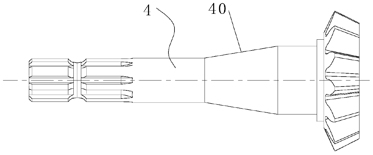
[0048] On the basis of Embodiment 1, when the speed of the vehicle is low and the retarder does not need to work, the spirally wound wire in the electromagnetic tube 3 is not energized, and then the turntable 5 is moved away under the action of the elastic restoring force of the compression spring 6. One side of the brake housing 20 moves, so that the conical hole 50 provided in the center of the turntable 5 and the conical surface 40 provided on the outer wall of the transmission shaft 4 are in a non-contact state, so that the transmission shaft 4 normally drives the rear axle of the car to work or when the vehicle speed is low. , the retarder does not work, which avoids the energy consumption problem caused by the rotor part always rotating with the high-speed transmission shaft, and reduces the noise and vibration of the transmission system during normal driving.

Embodiment 3

[0050] On the basis of Embodiment 1, the brake housing 20 is provided with an annular sinking platform 20-1, the inner end surface of the turntable 5 is provided with a spring seat 52 through rolling bearing rotation, and one end of the compression spring 6 is clamped with the annular sinking platform 20-1. Limit, the other end is clamped with the spring seat 52 to ensure that the compression spring 6 will not be subjected to the torsional force brought by the rotation of the turntable 5 when the turntable 5 rotates synchronously with the transmission shaft 4, ensuring the normal working form of the compression spring 6 .

[0051] The brake housing 20 is evenly provided with cooling holes 20-2, and a gap is provided between the brake housing 20 and the differential housing 1, which is beneficial to the friction and friction lining between the inner conical surface 40 and the conical hole 50. Dissipation of the heat generated by the friction between the sheet 22-4 and the inner...


PUM


Abstract

The invention discloses a mechanical vehicle transmission shaft retarder which is installed at the input end of a differential shell. The mechanical vehicle transmission shaft retarder comprises a brake, an electromagnetic tube, a transmission shaft, a rotary plate and a pressure spring, wherein the brake is composed of a brake shell, a fixed buckle seat, a brake shoe, a brake wheel cylinder, a small tension spring and a large tension spring, and the brake shell is fixedly connected with the differential shell; the electromagnetic tube is in interference fit connection with an inner hole in the center of the brake shell, the transmission shaft penetrates through the electromagnetic tube and the rotary plate and is in clearance rotation connection with the inner wall of the electromagnetictube, and the rotary plate is in axial sliding connection with the brake shell; and an annular sinking table is arranged in the brake shell, a spring seat is arranged on the inner end face of the rotary plate, one end of the pressure spring is clamped and limited with the annular sinking table, and the other end of the pressure spring is clamped and limited with the spring seat. The mechanical contact type retarder can achieve braking by adopting a double-friction pair, so that the energy consumption problem caused by high-speed rotation of the rotor part along with the transmission shaft is avoided; and the structure is simple, the cost is low, the maintenance is convenient to achieve, and not only is the running safety improved, but also the cost of the retarder for a vehicle is reduced.

Description

technical field [0001] The invention belongs to the technical field of retarders, and in particular, the invention relates to a mechanical vehicle transmission shaft retarder. Background technique [0002] The eddy current retarder is an auxiliary braking device for automobiles, commonly known as an electric brake. It is characterized by high braking strength and easy control. [0003] The eddy current retarder is installed between the car drive axle and the gearbox, and realizes non-contact braking through the principle of electromagnetic induction. It is an auxiliary braking system and a necessary supplement to the braking system, but it cannot replace the main braking system. [0004] The eddy current retarder is generally composed of a stator, a rotor and a fixed bracket. The working principle of the existing eddy current retarder is: when the retarder is working, the stator coil is energized to generate a magnetic field, and the rotor rotates together with the transm...

Claims


Application Information

Patent Timeline
IPC IPC(8): F16D51/20F16D65/08F16D65/14F16D65/827F16D123/00F16D121/04F16D121/20F16D125/02
CPCF16D51/20F16D65/14F16D65/08F16D65/827F16D2123/00F16D2121/20F16D2121/04F16D2051/001F16D2125/02
Inventor 朱益荣董朝秀
Owner 朱益荣
Why Eureka
Eureka Blog
Learn More