Refrigeration system with drying function, drying device and operation control method

A technology of refrigeration system and drying function, which is applied in the field of refrigeration system and drying device with drying function, and can solve problems such as the inability to realize efficient operation of the system in the drying stage

Pending Publication Date: 2019-09-06
GREE ELECTRIC APPLIANCES INC
View PDF0 Cites 2 Cited by
  • Summary
  • Abstract
  • Description
  • Claims
  • Application Information

AI Technical Summary

Problems solved by technology

[0003] Therefore, the existing technology cannot realize the problem of efficien

Method used


Image

  • Refrigeration system with drying function, drying device and operation control method
  • Refrigeration system with drying function, drying device and operation control method

Examples


Embodiment 1

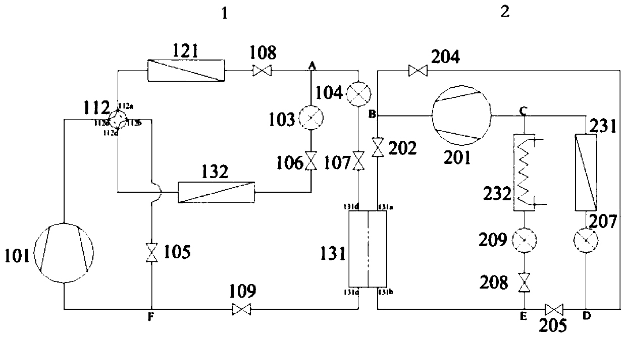
[0029] Such as figure 1 As shown, a refrigeration system with a drying function includes a first subsystem 1 and a second subsystem 2. The two subsystems are stacked together through a condensing evaporator 131. The refrigerant in the first subsystem is preferably medium High-temperature refrigerants, whose critical temperature is not higher than 200°C, can be one or a combination of two or more of the following: R134(A), R1234ze(Z), R1234ze(E), R1233zd(E), R245fa; The refrigerant in the second subsystem is preferably normal temperature or low temperature refrigerant, its critical temperature is not higher than 120°C, and it can be one or a combination of two or more: R32, R410A, R290.

[0030] The specific cooling system optimization scheme is as follows:

[0031] The first sub-system 1 includes a first refrigeration cycle formed by sequentially connecting the first compressor 101, the first heat exchanger 121, the first throttling device 104, the condensing evaporator 131 a...

Embodiment 2

[0048] An example of an operation control method for the refrigeration system in Embodiment 1 has the following control:

[0049] When the temperature Tin of the drying room is less than the preset temperature T1 and defrosting is not required, the temperature inside the drying room is relatively low. At this time, the cascade heat pump cycle can be used to quickly heat up the drying room, so that the first subsystem 1 and the second subsystem 2 Operation, control the valve of the first subsystem so that the flow direction of the refrigerant in the first subsystem 1 is the first compressor 101, the first heat exchanger 121, the first throttling device 104, the condensing evaporator 131, the evaporator side channel and The first compressor, the flow direction of the refrigerant in the second subsystem are the second compressor, the condenser side channel of the condensing evaporator, the third throttling device, the evaporator and the second compressor.

[0050] When the drying...

Embodiment 3

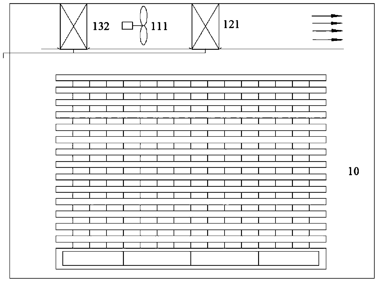
[0054] Such as figure 2 As shown, a drying device has a drying room and a refrigeration system, adopts the refrigeration system with drying function or the operation control method of the above-mentioned embodiment, and the first heat exchanger 121 and the second heat exchanger 132 are arranged in the drying in the room.


PUM

PropertyMeasurementUnit
Critical temperatureaaaaaaaaaa

Abstract

The invention relates to a refrigeration system, in particular to a refrigeration system with a drying function, a drying device and an operation control method. Through switching between single-stageheat pump circulation and cascade heat pump circulation, as well as combination between the open heating mode and the closed dehumidification mode, efficient operation of the whole heat pump drying process is realized; an auxiliary heater meets the heat required for continuous heating in the defrosting process, the continuous heating process is ensured, and the problem that the heating process isslow due to defrosting is avoided; and the reversible circulation of the air supply mode is realized by changing the flowing direction of a refrigerant, and thus the phenomenon of non-uniform dryingcaused by complicated air flue design and unidirectional air supply is avoided.

Description

technical field [0001] The invention relates to a refrigeration system, in particular to a refrigeration system with a drying function, a drying device and an operation control method. Background technique [0002] When using refrigeration system technology to dry materials, if the drying temperature is higher than 80°C, conventional air source heat pumps (except CO2 heat pumps) cannot achieve high-efficiency operation under high temperature rise. At this time, cascade cycles or multi-stage compression cycles are generally used. The cascade heat pump connects the two heat pump systems through the condensing evaporator. While meeting the demand for high heating temperature under the condition of large temperature rise, it also solves the problems of system design difficulties and compressor oil equalization problems that may exist in multi-stage compression. However, the existing technology does not take into account the high-efficiency operation of the system at different dr...

Claims


Application Information

Patent Timeline
IPC IPC(8): F25B7/00F25B41/04F25B41/06F25B49/02F26B9/02F26B21/00F26B21/04F26B21/08F25B41/20F25B41/30
CPCF25B7/00F25B49/022F26B9/02F26B21/002F26B21/004F26B21/04F26B21/086F25B2600/2513F25B2600/021F25B41/31F25B41/20
Inventor 郑波吕如兵黄健贵梁祥飞
Owner GREE ELECTRIC APPLIANCES INC
Why Eureka
Try Eureka