Model collision detection method and device based on BIM technology and electronic equipment

A collision detection and model technology, applied in the field of data processing, can solve the problem of high system resource occupancy, and achieve the effect of reducing memory occupancy

Pending Publication Date: 2019-09-06
BAOYE HUBEI CONSTR ENG GRP
View PDF4 Cites 13 Cited by
  • Summary
  • Abstract
  • Description
  • Claims
  • Application Information

AI Technical Summary

Problems solved by technology

It can achieve the effect of checking the collision situation in the model without loading the target model, so as to solve the problem of high occupation of system resources

Method used


Image

  • Model collision detection method and device based on BIM technology and electronic equipment
  • Model collision detection method and device based on BIM technology and electronic equipment
  • Model collision detection method and device based on BIM technology and electronic equipment

Examples


Embodiment 1

[0058] In order to facilitate the understanding of this embodiment, firstly, an electronic device implementing the BIM technology-based model collision detection method disclosed in the embodiment of the present application is introduced in detail.

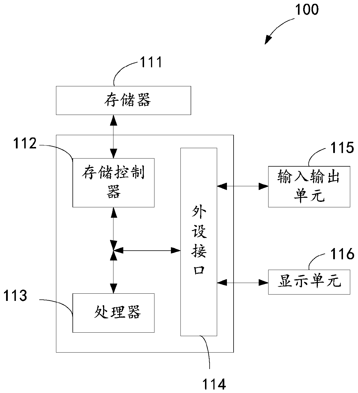
[0059] Such as figure 1 Shown is a block diagram of the electronic device. The electronic device 100 may include a memory 111 , a storage controller 112 , a processor 113 , a peripheral interface 114 , an input and output unit 115 , and a display unit 116 . Those of ordinary skill in the art can understand that, figure 1 The shown structure is only for illustration, and does not limit the structure of the electronic device 100 . For example, the electronic device 100 may also include a ratio figure 1 more or fewer components than shown in, or with figure 1 Different configurations are shown.

[0060] The memory 111 , storage controller 112 , processor 113 , peripheral interface 114 , input / output unit 115 and display unit 116...

Embodiment 2

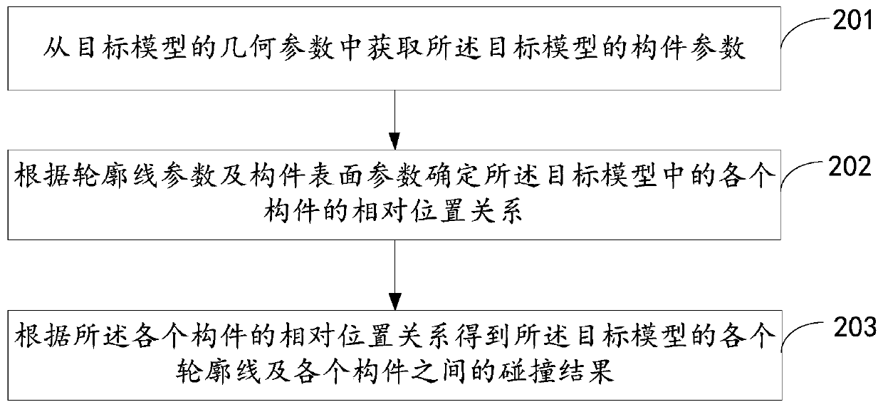
[0068] see figure 2 , is a flow chart of the BIM technology-based model collision detection method provided by the embodiment of the present application. The following will be figure 2 The specific process shown will be described in detail.

[0069] Step 201, obtaining component parameters of the target model from geometric parameters of the target model.

[0070] Wherein, the component parameters include contour line parameters and component surface parameters of the target model.

[0071] Optionally, the above-mentioned component parameters include the coordinates of each component, the size of the component, the cooperation mode of each component, and the like.

[0072] In an example, the above-mentioned target model may be a building information model pre-stored in the electronic device. In an optional example, the building information model may be a three-dimensional CAD (Computer Aided Design, computer-aided design) model.

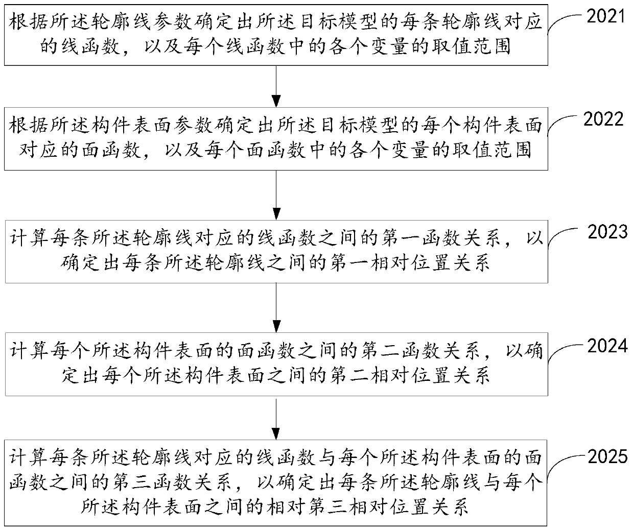
[0073] Step 202, determine the relative...

Embodiment 3

[0143] Based on the same application idea, the embodiment of this application also provides a model collision detection device based on BIM technology corresponding to the model collision detection method based on BIM technology. The model collision detection method based on BIM technology provided in the embodiment is similar, therefore, the implementation of the model collision detection device based on BIM technology in this embodiment can refer to the implementation of the model collision detection method based on BIM technology, and the repetition will not be repeated. .

[0144] see Figure 5 , is a schematic diagram of the functional modules of the BIM technology-based model collision detection device provided in the embodiment of the present application. Each module in the model collision detection device in this embodiment can be used to execute each step in the above method embodiment. The model collision detection device includes: an acquisition module 301, a dete...


PUM


Abstract

The invention provides a model collision detection method and device based on a BIM technology and electronic equipment, and the method comprises the steps: obtaining the component parameters of a target model from the geometric parameters of the target model, and enabling the component parameters to comprise the contour line parameters and the component surface parameters of the target model; determining a relative position relationship of each component in the target model according to the contour line parameters and the component surface parameters; and obtaining each contour line of the target model and a collision result between the components according to the relative position relationship of the components. Therefore, the collision relationship between the components of the target model can be determined under the condition that the target model is not loaded.

Description

technical field [0001] The present application relates to the technical field of data processing, in particular, to a BIM-based technology-based model collision detection method, device and electronic equipment. Background technique [0002] At present, buildings are generally simulated using architectural models before they are constructed. The architectural model is a relatively complex model. When using the architectural model, it is necessary to load the entire architectural model to achieve collision detection, which may occupy a large amount of computer system resources. Contents of the invention [0003] In view of this, the purpose of the embodiments of the present application is to provide a BIM technology-based model collision detection method, device and electronic equipment. It can achieve the effect of checking the collision situation in the model without loading the target model, so as to solve the problem of high occupation of system resources. [0004] In...

Claims


Application Information

Patent Timeline
Patent Type & Authority Applications(China)
IPC IPC(8): G06F17/50
CPCG06F30/13G06F30/20
Inventor 李峰徐旭东汪孙惠黄荣凯万菲姚攀王昕吴迪周成栋
Owner BAOYE HUBEI CONSTR ENG GRP
Why Eureka
Try Eureka