
Array substrate and display device

A technology for array substrates and display devices, applied in diodes, semiconductor devices, electrical components, etc., can solve the problems of affecting the screen ratio and the large aperture of the camera area, so as to increase the screen ratio, increase the light transmittance, and reduce the noise. The effect of light transmission area

Active Publication Date: 2019-09-06
WUHAN CHINA STAR OPTOELECTRONICS SEMICON DISPLAY TECH CO LTD
View PDF6 Cites 48 Cited by
  • Summary
  • Abstract
  • Description
  • Claims
  • Application Information

AI Technical Summary

Problems solved by technology

[0005] The present application provides an array substrate and a display device, which can solve the problem that the aperture of the camera area of ​​the display device of the existing under-screen camera is relatively large, which affects the screen-to-body ratio

Method used


Image

  • Array substrate and display device
  • Array substrate and display device
  • Array substrate and display device

Examples


Embodiment Construction

[0029] The following descriptions of the various embodiments refer to the accompanying drawings to illustrate specific embodiments that the present application can be used to implement. The directional terms mentioned in this application, such as [top], [bottom], [front], [back], [left], [right], [inside], [outside], [side], etc., are for reference only The orientation of the attached schema. Therefore, the directional terms used are used to illustrate and understand the application, but not to limit the application. In the figures, structurally similar elements are denoted by the same reference numerals.

[0030] This application is aimed at the technical problem that the existing under-screen camera display device has a relatively large space occupied by the camera area and affects the screen-to-body ratio. This embodiment can solve this defect.

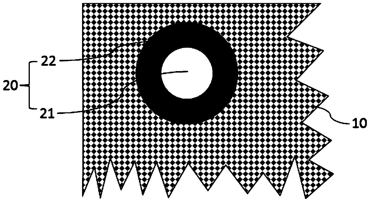
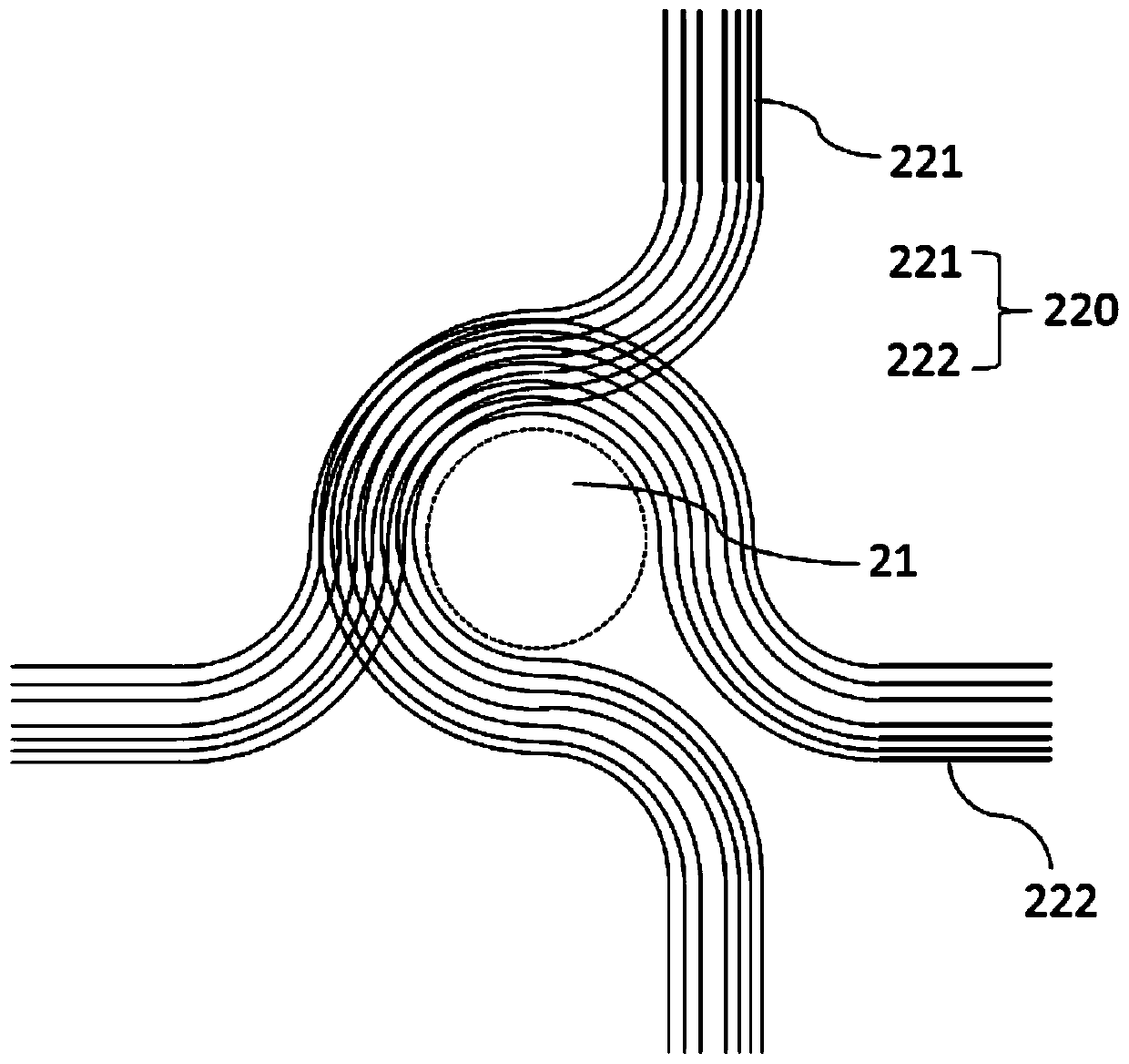
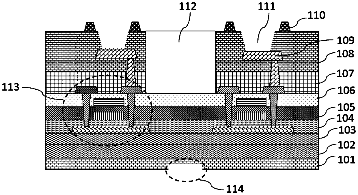
[0031] Such as figure 1 As shown in , is a partial top view of the array substrate provided by the embodiment of the present a...


PUM


Abstract

The invention provides an array substrate and a display device. The array substrate comprises a substrate, and a thin film transistor layer, a planarization layer and a pixel defining layer which aresequentially prepared on the substrate; a camera area is arranged in a range, corresponding to a display area, of the substrate; the camera area comprises a first blind hole and a wire area at the periphery of the first blind hole; the first blind hole is used for exposing a camera arranged on the back surface of the substrate; a signal wire and a second blind hole are arranged in the wire area; and the second blind hole avoids the arrangement of the signal wire and is used for increasing the light transmittance of the wire area. Therefore, the light-tight area of the camera area is reduced, and the screen-to-body ratio is improved.

Description

technical field [0001] The present application relates to the field of display technology, in particular to an array substrate and a display device. Background technique [0002] OLED (Organic Light-Emitting Diode, Organic Light-Emitting Diode) display device has thin, light, wide viewing angle, active light emission, continuously adjustable light color, low cost, fast response speed, low energy consumption, low driving voltage, and operating temperature range Wide, simple production process, high luminous efficiency and flexible display, etc., have been listed as a promising next-generation display technology. [0003] How to increase the screen-to-body ratio to achieve a full screen has become a current hot topic. The existing design generally puts the camera module under the screen, and adopts the design of opening a hole in the display area to expose the camera, thereby increasing the screen-to-body ratio. However, Since the black wiring area at the edge of the hole can...

Claims


Application Information

Patent Timeline
Patent Type & Authority Applications(China)
IPC IPC(8): H01L27/12H01L27/32H01L21/84
CPCH01L27/1218H01L27/1262H10K59/12H10K59/1201H10K59/65H10K59/873H10K59/124H10K59/122H10K59/131H10K50/844
Inventor 郑敏周阳欧阳齐高洪
Owner WUHAN CHINA STAR OPTOELECTRONICS SEMICON DISPLAY TECH CO LTD
Learn More