Supercharge Your Innovation With Domain-Expert AI Agents!

ultrasonic device

An ultrasonic and circuit technology, used in measurement devices, re-radiation of sound waves, radio wave measurement systems, etc. The effect of detection accuracy

Active Publication Date: 2020-12-25
MURATA MFG CO LTD
View PDF7 Cites 0 Cited by
  • Summary
  • Abstract
  • Description
  • Claims
  • Application Information

AI Technical Summary

Problems solved by technology

[0003] When foreign matter such as mud adheres to the vibrating surface of the ultrasonic transducer or the adhered water droplets freeze, it may become impossible to properly transmit and receive waves by the ultrasonic vibrator
As a result, it may not be possible to accurately detect the presence of the object to be detected in front of the ultrasonic vibrator

Method used


Image

  • ultrasonic device
  • ultrasonic device
  • ultrasonic device

Examples


Embodiment approach 1

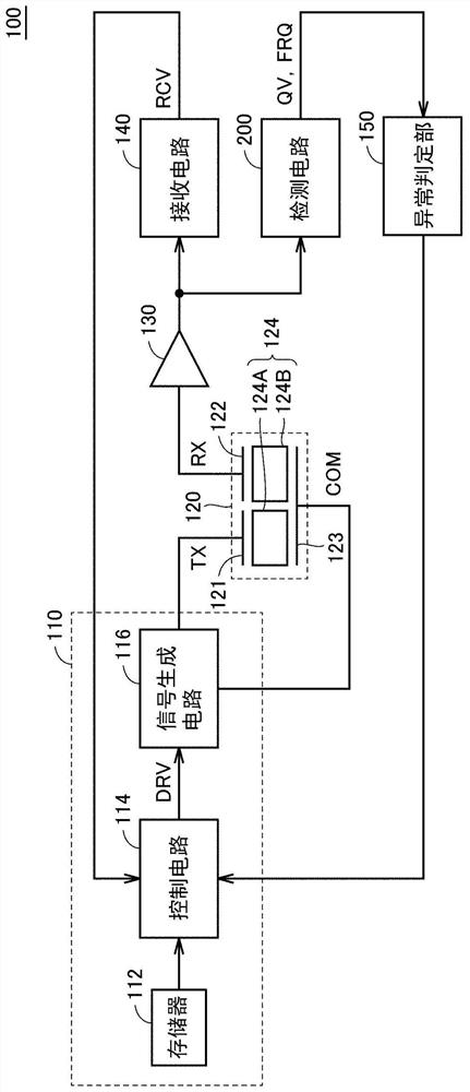
[0038] figure 1 It is a block diagram showing the overall configuration of the ultrasonic device 100 according to the first embodiment. refer to figure 1 , the ultrasonic device 100 includes a transmitting circuit 110 , an ultrasonic transducer 120 , an amplifier 130 , a receiving circuit 140 , an abnormality determination circuit 150 , and a detection circuit 200 .

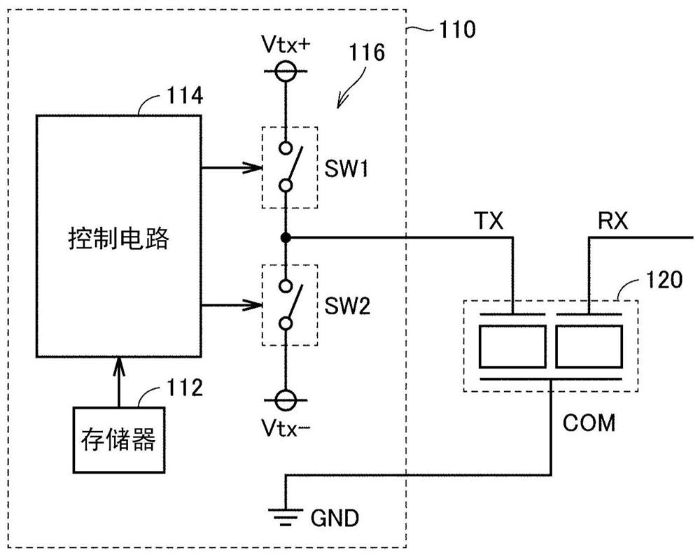
[0039] The transmission circuit 110 is a circuit for transmitting ultrasonic waves from the ultrasonic transducer 120 by driving the ultrasonic transducer 120 . The transmission circuit 110 includes a memory 112 , a control circuit 114 and a signal generation circuit 116 . The control circuit 114 reads the data stored in the memory 112 and outputs a control signal DRV suitable for driving the ultrasonic transducer 120 to the signal generation circuit 116 . The signal generating circuit 116 generates an AC voltage (ultrasonic pulse: transmission signal) from a DC voltage based on a control signal DRV output fro...

Deformed example 1

[0085] Figure 9 It is a diagram showing a modified example of the detection circuit of the ultrasonic device 100 according to the first embodiment. In the detection circuit 200A of Modification 1, it becomes the Figure 8 The resonant frequency measurement circuit 250 of the detection circuit 200 shown is further configured by adding a frequency dividing circuit 254 . refer to Figure 9 The resonance frequency measurement circuit 250A includes a comparator 251 , a frequency division circuit 254 , a counter 252 , and a frequency calculation circuit 253 . exist Figure 9 , without repeating the same Figure 8 A description of the element to repeat.

[0086] refer to Figure 9 , the frequency dividing circuit 254 divides the frequency of the reception signal output from the comparator 251 . The counter 252 calculates the period T of the reverberation signal based on the signal divided by the frequency division circuit 254 RES . Since the frequency division circuit 254 c...

Deformed example 2

[0088] Figure 10 It is a diagram showing a modified example in which the A / D conversion circuit 160 is further added to the front stage of the detection circuit 200 in the ultrasonic device 100 according to the first embodiment. exist Figure 10 In a modified example of , the signal processing in the detection circuit 200 is performed using a digital circuit.

[0089] It should be noted that the structure of the modification example 2 can also be combined with the structure of the modification example 1.


PUM


Abstract

The ultrasonic device (100) includes an ultrasonic transducer (120), a transmitting circuit (110), a receiving circuit (140), a Q value measuring circuit (210), and a frequency measuring circuit (250). The ultrasonic transducer is a three-terminal ultrasonic transducer having a transmitting electrode (121), a receiving electrode (122), and a common electrode (123). The transmission circuit outputs a drive signal to the transmission electrode and transmits ultrasonic waves from the ultrasonic transducer. The receiving circuit receives the received signal from the receiving electrode. The frequency measuring circuit measures the resonant frequency of the ultrasonic transducer based on the reverberation signal of the received signal. The Q value measuring circuit measures the Q value of the ultrasonic transducer based on the reverberation signal of the received signal.

Description

technical field [0001] The present invention relates to an ultrasonic device, and more specifically relates to a technique for measuring a Q value and a resonance frequency of a three-terminal ultrasonic transducer provided with a transmitting terminal and a receiving terminal independently. Background technique [0002] Ultrasonic devices that transmit ultrasonic waves from an ultrasonic transducer and receive reflected waves reflected by the target object by the ultrasonic transducer to measure the distance to the target object and the like are put into practical use. [0003] When foreign matter such as mud adheres to the vibrating surface of the ultrasonic transducer or adhered water droplets freeze, it may become impossible to properly transmit and receive waves by the ultrasonic vibrator. As a result, the presence of the object to be detected in front of the ultrasonic transducer may not be accurately detected. [0004] Japanese Patent No. 2998232 (Patent Document 1) ...

Claims


Application Information

Patent Timeline
Patent Type & Authority Patents(China)
IPC IPC(8): H04R3/00G01S7/52G01S7/521G01S7/526
CPCH04R3/00B06B1/0692B06B1/0215B06B2201/30B06B2201/40B06B1/0261G01S2007/52009G01S15/931G01S7/52004
Inventor 中尾元保渡边恒介
Owner MURATA MFG CO LTD
Features
  • R&D
  • Intellectual Property
  • Life Sciences
  • Materials
  • Tech Scout
  • Unparalleled Data Quality
  • Higher Quality Content
  • 60% Fewer Hallucinations
Learn More