Dressing mirror

A fitting mirror and frame technology, which is applied in the field of decoration design, can solve problems such as increasing the area of ​​non-luminous parts on the surface of mirror products, reducing customer satisfaction with fitting experience, limiting customers' observation field of view, etc., achieving bright and clear images, reducing Thickness, effect of improving satisfaction

Inactive Publication Date: 2019-09-10
上海臻旺装饰设计工程有限公司
View PDF10 Cites 1 Cited by
  • Summary
  • Abstract
  • Description
  • Claims
  • Application Information

AI Technical Summary

Problems solved by technology

[0004] In the above-mentioned patents, since the edge of the mirror surface is provided with a main body frame, and the LED light-emitting lamp is embedded in the main watch frame, the width of the main body frame is increased, and the area of ​​the non-luminous part on the surface of the mirror surface product is increased, especially for a dressing mirror, a large width The main frame will limit the customer's observation field of view and reduce the satisfaction of customers' fitting experience

Method used


Image

  • Dressing mirror
  • Dressing mirror
  • Dressing mirror

Examples


Embodiment 1

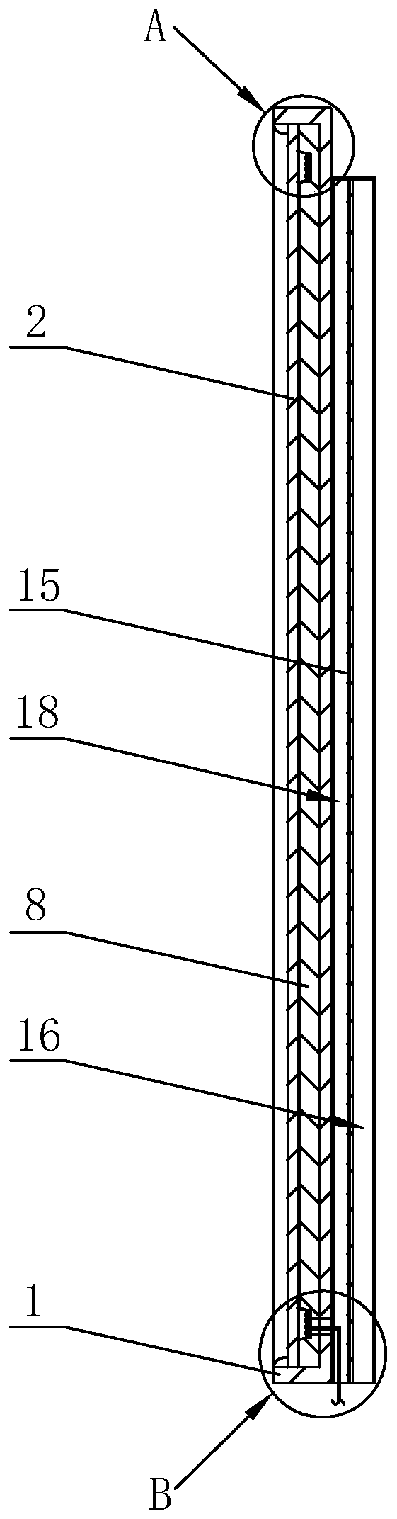
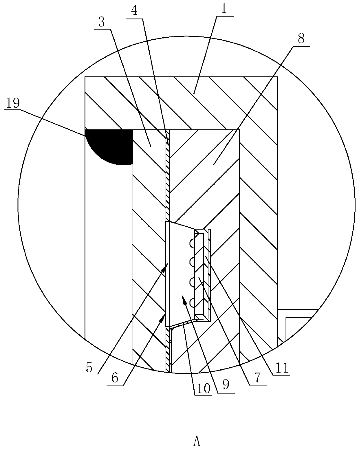
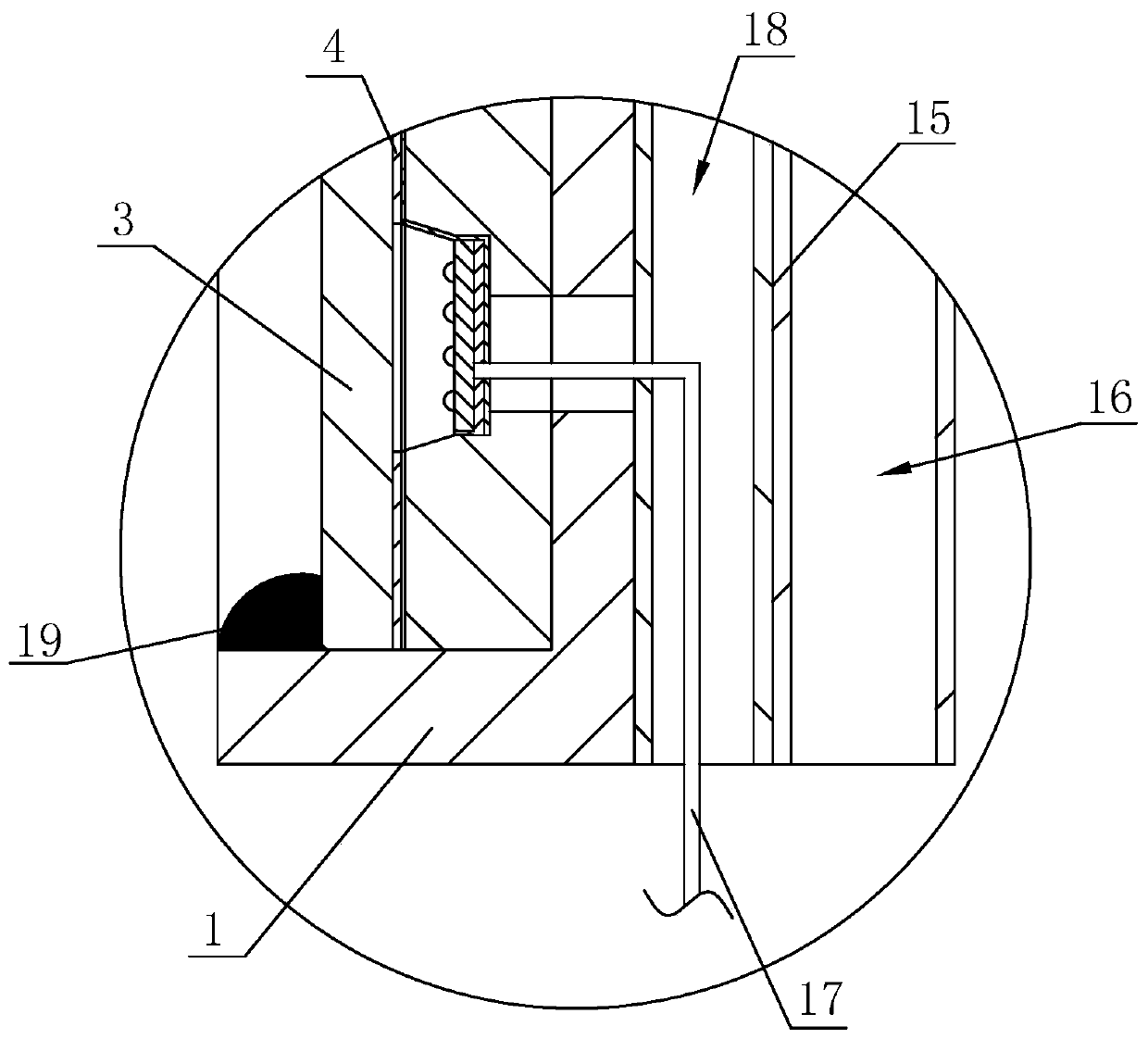
[0041] a fitting mirror such as figure 1 and figure 2 As shown, it includes a wooden mirror frame 1, an opening structure is formed on one side of the mirror frame 1, a mirror surface 2 is clamped and connected in the opening of the mirror frame 1, and a clip 19 for clamping the mirror surface 2 is fixed at the opening of the mirror frame 1 along its edge. The mirror surface 2 includes a glass layer 3 that is clamped in the opening of the mirror frame 1. The side of the glass layer 3 close to the bottom of the opening of the mirror frame 1 is coated with a coating layer 4. Ring 5, the surface of the glass layer 3 is processed by a sandblasting machine at the light-transmitting ring 5 to form a sand-blasting surface 6, and a light-emitting element 7 is fixed in the mirror frame 1 along the light-transmitting ring 5, and the light-emitting element 7 is an LED lamp. When in use, the user stands in front of the mirror surface 2 to try on the clothes, and the light-emitting eleme...

Embodiment 2

[0045] a fitting mirror such as Figure 4 and Figure 5 As shown, the buffer layer 8 is provided with a heat dissipation hole 12 at the bottom of the placement groove 9, the heat dissipation hole 12 penetrates the buffer layer 8 and the mirror frame 1, the heat dissipation hole 12 is opened to further improve heat dissipation, and the glass layer 3 is opened on the peripheral side to facilitate the glass layer 3. To the chamfer 13 in the mirror frame 1, the glass layer 3 is coated with a coating 4 on the chamfer 13, the surface of the glass layer 3 is provided with a groove 14 along the light-transmitting ring 5, the bottom of the groove 14 is arc-shaped, and the groove 14 The bottom is processed by a sandblasting machine to form a sandblasting surface 6 . When in use, a sandblasting surface 6 is arranged at the bottom of the groove 14, so that the light emitted by the light-emitting element 7 can be emitted at a larger scattering angle, so as to avoid excessive concentration...


PUM


Abstract

The invention discloses a dressing mirror, and relates to the technical field of decorative design. The dressing mirror comprises a mirror frame, and a mirror is arranged in an opening in one side ofthe mirror frame in a clamping manner; the mirror comprises a glass layer arranged in the opening of the mirror frame in a clamping manner, and a plated layer coats the side face, close to the bottomof the opening of the mirror frame, of the glass layer; and the edge of the mirror forms a light-pervious ring through removal of the plated layer, a sand blasting face is arranged at the position, with the light-pervious ring, of the surface of the glass layer, and a light-emitting part is arranged in the mirror frame along the light-pervious ring. Aiming at the problem that the width of a frameof a light-supplementing mirror is large in the prior art, the dressing mirror adopts the structure that the light-emitting part is arranged in the mirror frame, so that the thickness of the edge of the mirror frame is greatly reduced, the imaging area is improved, the view field of customers is increased, and further, the satisfaction degree of the cloths try-on experience of the customers is improved.

Description

technical field [0001] The invention relates to the technical field of decoration design, and more particularly, to a fitting mirror. Background technique [0002] Mirrors are commonly used objects in our daily life. In recent years, in order to improve the effect of mirror reflection imaging, the product design is usually to set up lights for fill light at the edge of the mirror surface. [0003] For the existing mirror surface that can be supplemented with light, such as the Chinese patent with the patent publication number CN206079492U, it discloses a cosmetic mirror with adjustable direction, the structure of which includes a light-transmitting layer, a mirror surface, a main frame, a universal head, a support rod, Light switch, anti-skid pad, rechargeable battery, base, charging socket, magnifying mirror, LED light, the mirror is set on the frame of the main body, the frame of the main body is fixedly connected to the universal head, the universal head is composed of a...

Claims


Application Information

Patent Timeline
Patent Type & Authority Applications(China)
IPC IPC(8): A47G1/02F21V33/00
CPCA47G1/02F21V33/004
Inventor 徐林邓广成
Owner 上海臻旺装饰设计工程有限公司
Why Eureka
Try Eureka