
Self-centering and synchronous clamping mechanism

A synchronous clamping and self-centering technology, applied in the direction of the chuck, etc., can solve the problems of the wedge-shaped synchronous clamping mechanism, such as complex structure, inconvenient operation, and inability to realize self-locking, and achieve the effect of compact structure, simple structure and reasonable layout

Inactive Publication Date: 2019-09-10
周冬冬
View PDF0 Cites 0 Cited by
  • Summary
  • Abstract
  • Description
  • Claims
  • Application Information

AI Technical Summary

Problems solved by technology

In order to maintain synchronization, multiple wedge-shaped mechanisms are usually driven by the same drive mechanism, and the motion is transmitted to each wedge-shaped mechanism through the power transmission mechanism, resulting in a complex structure of the wedge-shaped synchronous clamping mechanism
At the same time, the wedge-shaped synchronous clamping mechanism cannot realize self-locking when the stroke is large, and the operation is inconvenient

Method used


Image

  • Self-centering and synchronous clamping mechanism
  • Self-centering and synchronous clamping mechanism

Examples


Embodiment Construction

[0009] The present invention will be further described below through a specific embodiment in conjunction with the accompanying drawings.

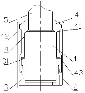
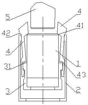
[0010] Such as Figure 1 to Figure 2 As shown, a self-centering synchronous clamping mechanism includes an ejector, a positioning member, a guide, and m claws, wherein m is a natural number, and m≥2; the m claws are along the outer surface of the workpiece Evenly arranged, the claws are provided with step 1 and step 2, ejectors are provided on the inside of the m claws, guides are provided on the outside of the ejectors, and positioning parts are provided on the outside of the m claws pieces.

[0011] In this embodiment, the claw is provided with a groove, and the guide is provided with a protrusion, and the groove and the protrusion adopt a clearance fit; the transition surface of the step 1 includes an inclined surface, a tapered surface, Arc-shaped surface; the transition surface of the step 2 includes an inclined surface, a tapered s...


PUM


Abstract

The invention discloses a self-centering and synchronous clamping mechanism. The self-centering and synchronous clamping mechanism comprises clamping jaws, ejecting parts, positioning parts and guiding parts, wherein a plurality of clamping jaws are uniformly arranged on the outer surface of a workpiece; the ejecting parts are arranged on the inner sides of the clamping jaws; the positioning partsare arranged on the outer sides of the clamping jaws. Through cooperation of the ejecting parts, the positioning parts and the clamping jaws, all the clamping jaws synchronously swing to achieve selfcentering and synchronous clamping of the workpieces. The self-centering and synchronous clamping mechanism is simple in structure and convenient and rapid to operate.

Description

technical field [0001] The invention relates to a synchronous clamping mechanism, in particular to a self-centering synchronous clamping mechanism. Background technique [0002] The common wedge-shaped synchronous clamping mechanism drives several wedge-shaped mechanisms to move synchronously through the driving mechanism to realize the clamping of the workpiece. In order to maintain synchronization, multiple wedge-shaped mechanisms are usually driven by the same drive mechanism, and the motion is transmitted to each wedge-shaped mechanism through a power transmission mechanism, resulting in a complex structure of the wedge-shaped synchronous clamping mechanism. At the same time, the wedge-shaped synchronous clamping mechanism cannot realize self-locking when the stroke is large, and the operation is inconvenient. . Contents of the invention [0003] The technical problem to be solved by the present invention is to provide a self-centering synchronous clamping mechanism,...

Claims


Application Information

Patent Timeline
IPC IPC(8): B23B31/103
CPCB23B31/103
Inventor 不公告发明人
Owner 周冬冬
Learn More