Wheel leg type humanoid robot with internal oil flowing

A humanoid and robot-like technology, applied in manipulators, motor vehicles, program-controlled manipulators, etc., can solve problems affecting the flexibility of robot movement, long hose layout, complexity, etc., to avoid shortened motor life and pipeline wear failures The effect of reduction and weight reduction

Active Publication Date: 2019-09-10
HARBIN INST OF TECH
View PDF7 Cites 6 Cited by
  • Summary
  • Abstract
  • Description
  • Claims
  • Application Information

AI Technical Summary

Problems solved by technology

[0005] In order to solve the problem that the existing hydraulically driven robot uses a rubber hose to connect the hydraulic drive unit and the power unit, the hose is long and the layout is complicated, which affects the flexibility of the robot’s movement, and provides a wheel with internal oil. legged humanoid robot

Method used


Image

  • Wheel leg type humanoid robot with internal oil flowing
  • Wheel leg type humanoid robot with internal oil flowing
  • Wheel leg type humanoid robot with internal oil flowing

Examples


specific Embodiment approach 1

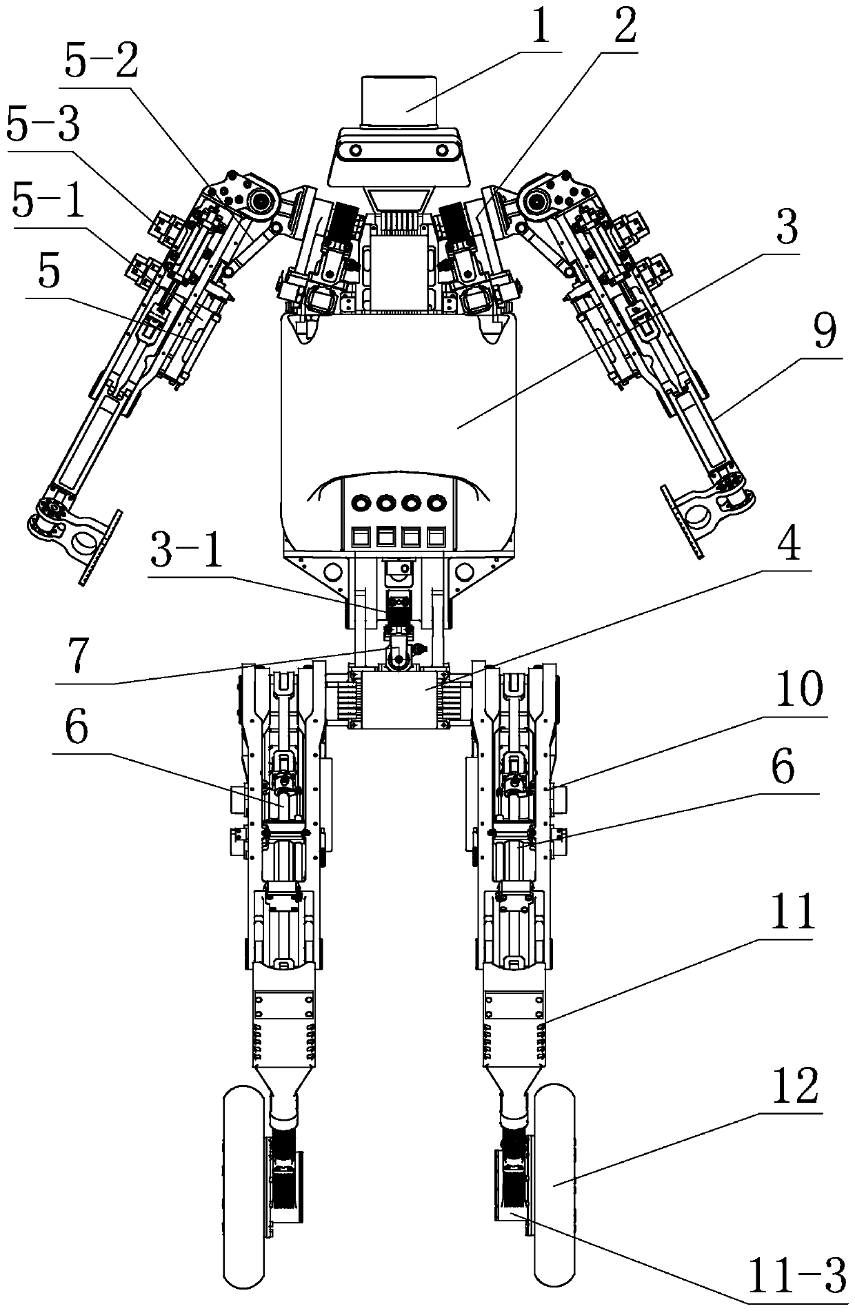
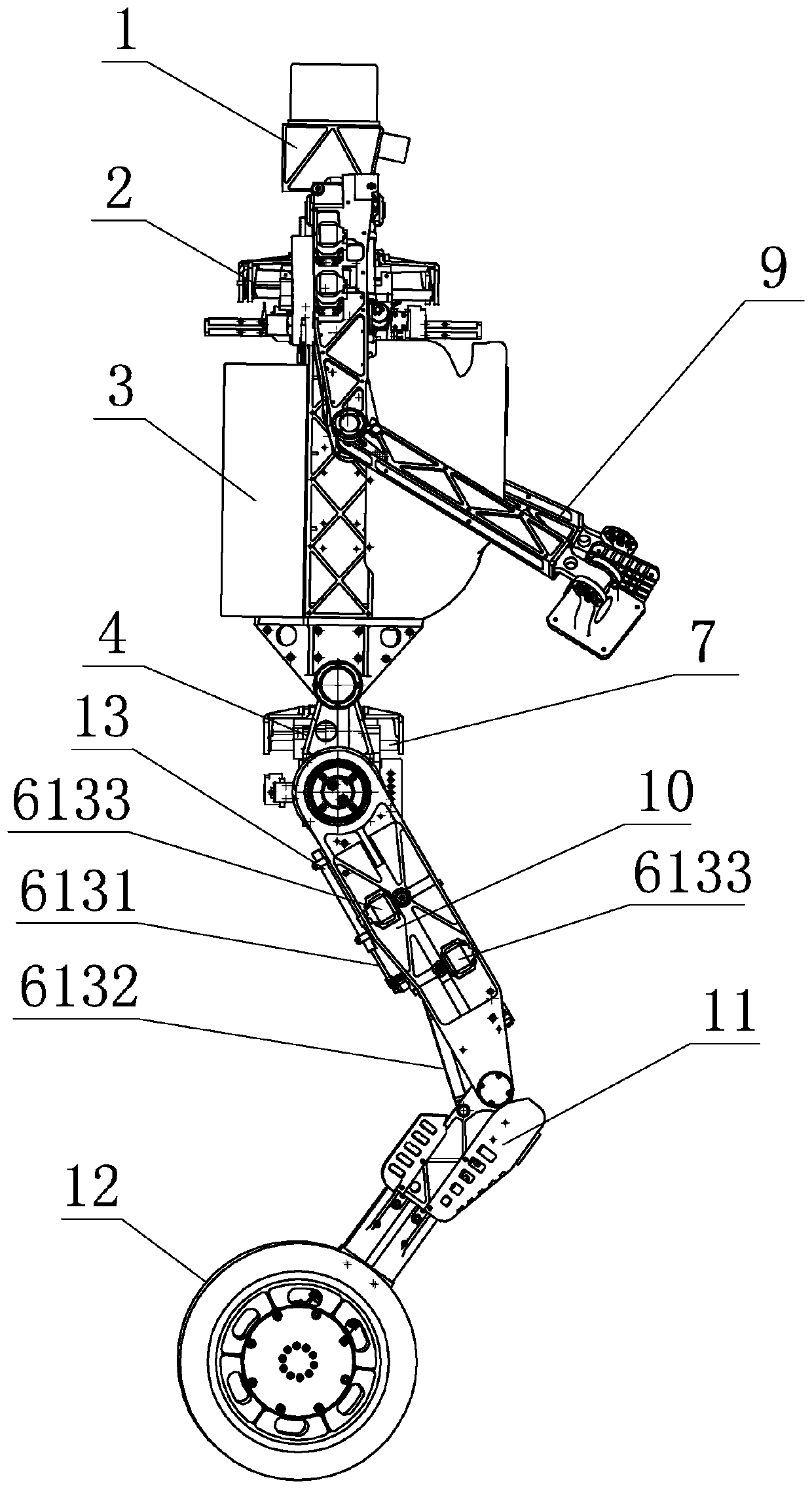
[0050] Specific implementation mode one: combine figure 1 and figure 2 To illustrate this embodiment, this embodiment includes a head 1, a shoulder 2, a body 3, a hip pelvis 4, a first hydraulic linkage assembly 5, a second hydraulic linkage assembly 6, and a third hydraulic linkage assembly 13. Hydraulic cylinder 7, two mechanical arms 9, two thighs 10, two shanks 11 and two driving wheels 12;

[0051] The head 1, the shoulder 2 and the body 3 are fixed together from top to bottom in sequence, the body 3 is hinged with the hip and pelvis 4 and driven by the hydraulic cylinder 7, and each mechanical arm 9 is hinged on the shoulder 2 and passed through the first The hydraulic link assembly 5 can be driven to swing left and right, each thigh 10 is hinged to the hip pelvis 4 and driven by the second hydraulic link assembly 6 so that each thigh 10 can swing back and forth, and each calf 11 is hinged to each thigh 10 And driven by the third hydraulic linkage assembly 13 so that ...

specific Embodiment approach 2

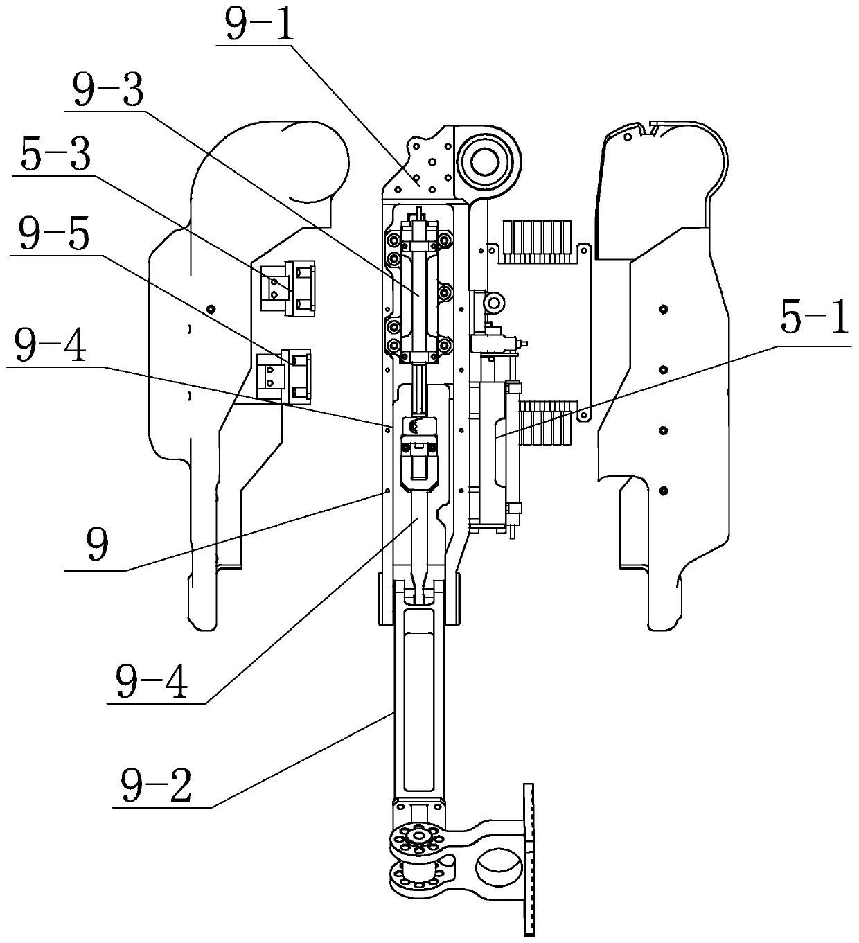
[0055] Specific implementation mode two: combination image 3 To illustrate this embodiment, each mechanical arm 9 in this embodiment includes a boom 9-1, a small arm 9-2, a third hydraulic cylinder 9-3, a third connecting rod 9-4 and a third hydraulic servo valve 9- 5;

[0056] The two booms 9-1 are hinged on both sides of the shoulder 2, the forearm 9-2 and the boom 9-1 are hinged together, and the third hydraulic cylinder 9-3 and the third hydraulic servo valve 9-5 are respectively fixed on On the boom 9-1, one end of the third connecting rod 9-4 is hinged with the forearm 9-2, and the other end of the third connecting rod 9-4 is hinged with the execution end of the third hydraulic cylinder 9-3 to make the forearm 9-2 swings on the big arm 9-1,

[0057] The big arm 9-1 and the shoulder 2 on each mechanical arm 9 are processed with a third oil circuit and a fourth oil circuit, and the oil outlet of the fourth oil circuit passes through the hydraulic pipe and the inlet of t...

specific Embodiment approach 3

[0059] Specific implementation mode three: combination Figure 4 To illustrate this embodiment, the shoulder 2 of this embodiment is provided with two rotating shafts 2-1 and two swing arm hydraulic cylinders 2-2, and each swing arm hydraulic cylinder 2-2 communicates with an external hydraulic system through a hydraulic pipe. And each swing arm hydraulic cylinder 2-2 is provided with a hydraulic servo valve on the hose that communicates with the external hydraulic system, and each rotating shaft 2-1 is provided with a first gear 2-3, and each mechanical arm 9 passes through the first gear 2-3. An articulated shaft 15 is hinged to each rotating shaft 2-1 and driven by the first hydraulic linkage assembly 5 to swing left and right, each swing arm hydraulic cylinder 2-2 is fixed with a first guide rail, and the first rack 2-4 slides It is arranged on the first guide rail and fixed to the execution end of the swing arm hydraulic cylinder 2-2, and the first rack 2-4 and the first ...


PUM


Abstract

The invention discloses a wheel leg type humanoid robot with internal oil flowing, relates to the technical field of robots, and aims to solve the problems that when a hydraulic driving unit and a power unit are connected by adopting a rubber hose, the hose is long, the pipe arrangement is complex, and the movement flexibility of a conventional hydraulically-driven robot is influenced. The humanoid robot comprises a head, shoulders, a body, a hip pelvic bone, a first hydraulic connecting rod assembly, a second hydraulic connecting rod assembly, a third hydraulic connecting rod assembly, a hydraulic cylinder, two mechanical arms, two thighs, two shanks and two driving wheels. The head, the shoulders and the body are sequentially and fixedly connected together from top to bottom; the body ishinged to the hip pelvic bone and driven by the hydraulic cylinder, each mechanical arm is hinged to the corresponding shoulder and driven by the first hydraulic connecting rod assembly to swing leftwards and rightwards, and each thigh is hinged to the hip pelvic bone and driven by the second hydraulic connecting rod assembly to swing forwards and backwards. Each joint adopts a hose-free oil way,so that the pipeline abrasion fault is greatly reduced, and the safety and the reliability of the whole machine are improved.

Description

technical field [0001] The invention relates to a humanoid robot, in particular to a wheel-legged humanoid robot with internal oil flow. Background technique [0002] For a long time, leg-footed robots have been used as a very effective solution for rugged and complex terrain and non-continuous ground such as step ridges. Traditional wheeled or tracked robots have strong mobility on flat and continuous ground. , but the ability to pass through complex discontinuous ground is weak. Although legged robots can flexibly adapt to various complex terrains, their stability control is difficult and their walking speed is slow on flat ground. The goal of the wheel-legged composite robot is to combine the respective advantages of the wheeled robot and the legged robot, that is, the high mobility of the wheeled movement and the strong adaptability of the leg-footed movement, so that the wheel-legged composite robot has both the ability to move quickly on flat ground and the ruggedness...

Claims


Application Information

Patent Timeline
Patent Type & Authority Applications(China)
IPC IPC(8): B62D57/028B25J9/00
CPCB25J9/0006B62D57/028
Inventor 付宜利李旭封海波周海涛张松源
Owner HARBIN INST OF TECH
Why Eureka
Try Eureka