Multi-layer chain transmission cooling device for food

A technology of a cooling device and a chain drive mechanism, which is applied to cooling fluid circulation devices, household refrigeration devices, coolers, etc., can solve the problem of increasing the manufacturing cost of the cooling box 1, increasing the energy loss of the cooling airflow, increasing the components and production costs, etc. problems, to achieve the effect of improving cooling efficiency and cooling effect, reducing energy loss, and reducing parts

Pending Publication Date: 2019-09-10
苏州姑苏食品机械有限公司
View PDF0 Cites 4 Cited by
  • Summary
  • Abstract
  • Description
  • Claims
  • Application Information

AI Technical Summary

Problems solved by technology

[0005] 1) Due to the inherent problem of the working mode of the axial flow fan 4, the mechanism relies too much on the function of the internal return air cover 7 to complete the circulation of the cooling air flow, but the energy of the cooling air flow is relatively large after being guided and rebounded by the return air cover 7 loss, resulting in insufficient cooling air flow into the multi-layer chain transmission mechanism 2, and finally the overall cooling efficiency of the device is not high, and the effect is not good;
[0006] 2) In order to better guide the cooling airflow generated by the cooling mechanism into the interior of the multi-layer chain transmission mechanism 2, it is often necessary to install the air outlet guide cover 8 near the upper part of the multi-layer chain transmission mechanism 2, and pass through the return air cover 7 The rebounded cooling airflow gathers and guides into the interior of the multi-layer chain transmission mechanism 2, which increases the cost of components and production, and further consumes the energy of the cooling airflow
[0007] 3) The axial flow fan 4 and the evaporator 5 are arranged horizontally, which takes up more space, which not only makes the length of the air duct inside the cooling box 1 longer, increases the energy loss of the cooling airflow, but also wastes materials and increases the cooling capacity of the cooling box. 1 manufacturing cost

Method used


Image

  • Multi-layer chain transmission cooling device for food
  • Multi-layer chain transmission cooling device for food

Examples


Embodiment

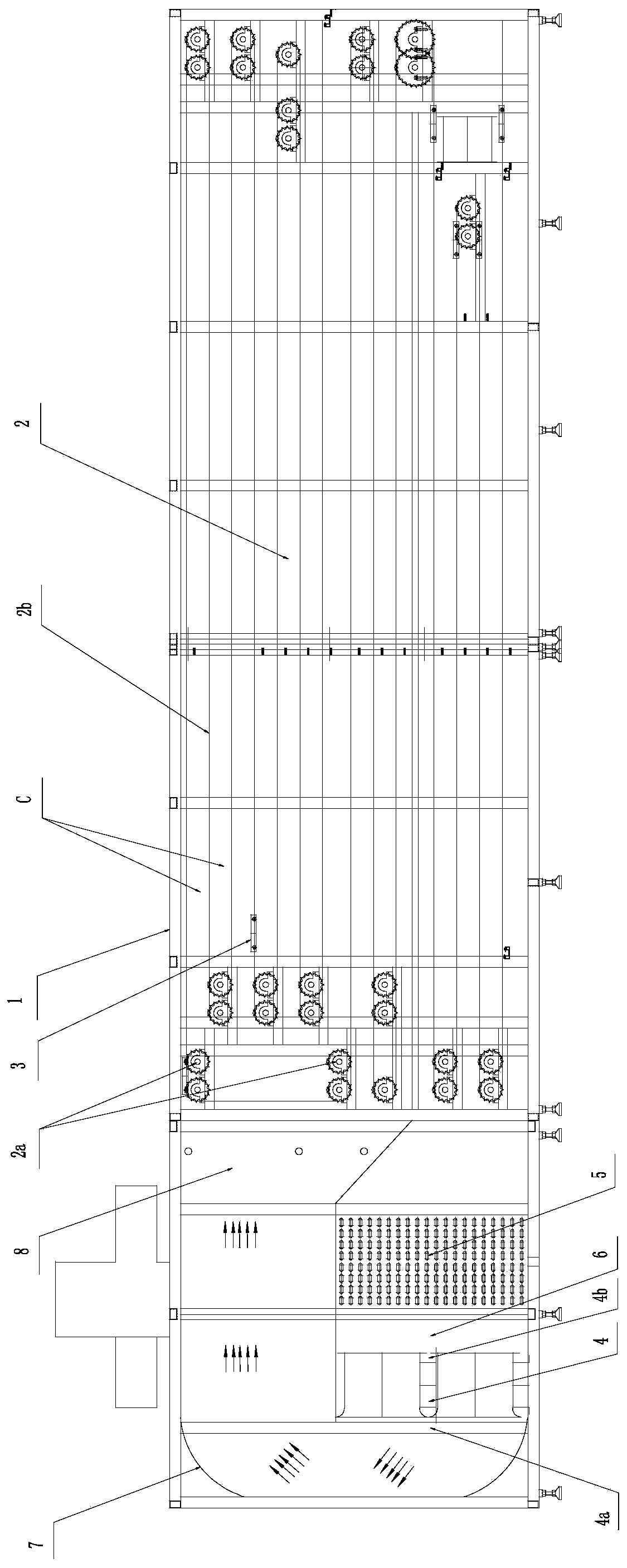
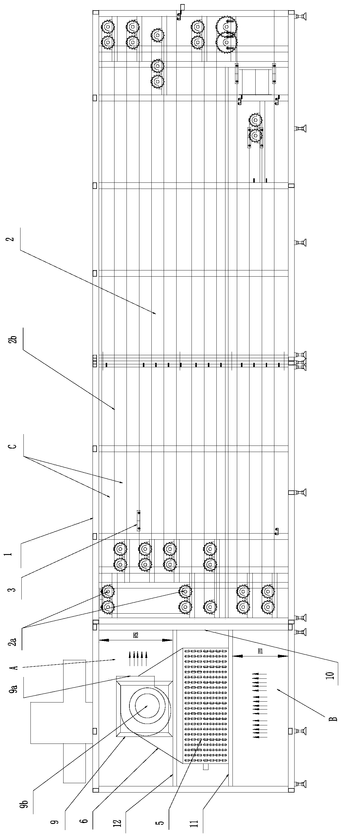
[0024] Embodiment: combine below figure 2 Shown, this specific implementation mode provided by the present invention is described in detail as follows:

[0025] combine figure 2 This food multi-layer chain transmission cooling device provided by the present invention has a cooling box 1 and a multi-layer chain transmission mechanism 2 and a refrigeration mechanism located in the cooling box 1 as in the conventional technology, and the refrigeration mechanism is located in the multi-layer chain transmission. Agency 2 side. The difference is that we have improved the refrigeration mechanism, which is composed of a centrifugal fan 9, an evaporator 5 and an air guide cover 6. The cooling box 1 is provided with a support frame 10 between the multi-layer chain transmission mechanism 2 and the refrigeration mechanism. The support frame 10 and the inner wall of the cooling box 1 opposite to it are fixed with a first partition arranged from bottom to top. 11 and the second partiti...


PUM


Abstract

The invention discloses a multi-layer chain transmission cooling device for food. The multi-layer chain transmission cooling device for the food comprises a cooling box body and a multi-layer chain transmission mechanism and a refrigerating mechanism which are arranged in the cooling box body, and the refrigerating mechanism is located on one side of the multi-layer chain transmission mechanism. The multi-layer chain transmission cooling device for the food is characterized in that the refrigerating mechanism comprises a centrifugal fan, an evaporator and an air guiding cover, the evaporator and the centrifugal fan are fixed to the interior of the cooling box body by adopting a fixing structure, the centrifugal fan is located over the evaporator, an air return channel is arranged between an inlet of the evaporator and the multi-layer chain transmission mechanism arranged on one side of the evaporator, an outlet of the evaporator is connected with an axial air inlet of the centrifugal fan through the air guiding cover, and an air outlet of the centrifugal fan faces the multi-layer chain transmission mechanism arranged on one side of the evaporator. Compared with an original coolingdevice taking an axial flow fan as the core, the cooling efficiency is higher, the effect is better, the structure is simpler, and the manufacturing cost is lower.

Description

technical field [0001] The invention relates to a food multi-layer chain transmission cooling device. Background technique [0002] At present, in food production industries such as chocolate, energy bars, and sugar bars, it is usually necessary to cool and solidify the food after pouring. At present, the common cooling and solidification equipment is a multi-layer chain transmission cooling device, such as figure 1 As shown, the mechanism is mainly composed of a cooling box body 1 and a multi-layer chain transmission mechanism 2 and a refrigeration mechanism arranged in the cooling box body 1 . Among them, the multi-layer chain transmission mechanism 2 drives the chain 2b arranged in the shape of "己" to run through multiple sets of drive sprockets 2a designed longitudinally, so that the conveying plate 3 used to transport food on the chain 2b can take the "己"-shaped route, extending cooling path. The switching between the upper and lower chain layers of the conveying plat...

Claims


Application Information

Patent Timeline
Patent Type & Authority Applications(China)
IPC IPC(8): B65G17/06B65G17/38B65G23/06B65G69/20F25D19/00F25D17/04A23G7/02
CPCA23G7/02B65G17/065B65G17/38B65G23/06B65G69/20F25D17/045F25D19/00
Inventor 张伟
Owner 苏州姑苏食品机械有限公司
Why Eureka
Try Eureka