Rotary exhaust valve

An exhaust valve, valve cover technology, applied in the direction of lift valve, valve device, engine components, etc., can solve the problems of poor sealing, cracking or detachment of the cast rubber layer, etc. The effect of fragmentation, avoiding frequent downtime

Inactive Publication Date: 2019-09-10
SHANDONG IRON & STEEL CO LTD
View PDF4 Cites 1 Cited by
  • Summary
  • Abstract
  • Description
  • Claims
  • Application Information

AI Technical Summary

Problems solved by technology

[0004] During the use of the rotary exhaust valve, the valve cover is driven by the swing arm to impact the valve seat frequently, and the cast rubber layer will crack or fall off after frequent impact, resulting in poor sealing

Method used


Image

  • Rotary exhaust valve
  • Rotary exhaust valve
  • Rotary exhaust valve

Examples


Embodiment Construction

[0026] In order to make the purpose, technical solution and advantages of the present invention clearer, the technical solution of the present invention will be clearly and completely described below in conjunction with specific embodiments of the present invention and corresponding drawings. Apparently, the described embodiments are only some of the embodiments of the present invention, but not all of them. Based on the embodiments of the present invention, all other embodiments obtained by persons of ordinary skill in the art without making creative efforts fall within the protection scope of the present invention.

[0027] The technical solutions provided by the embodiments of the present invention will be described in detail below in conjunction with the accompanying drawings.

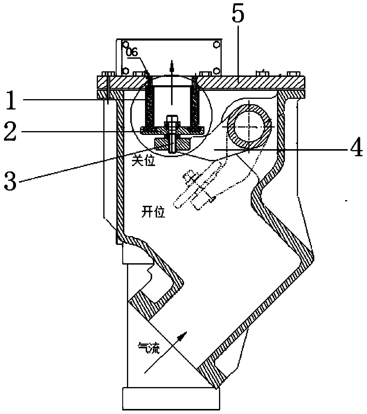
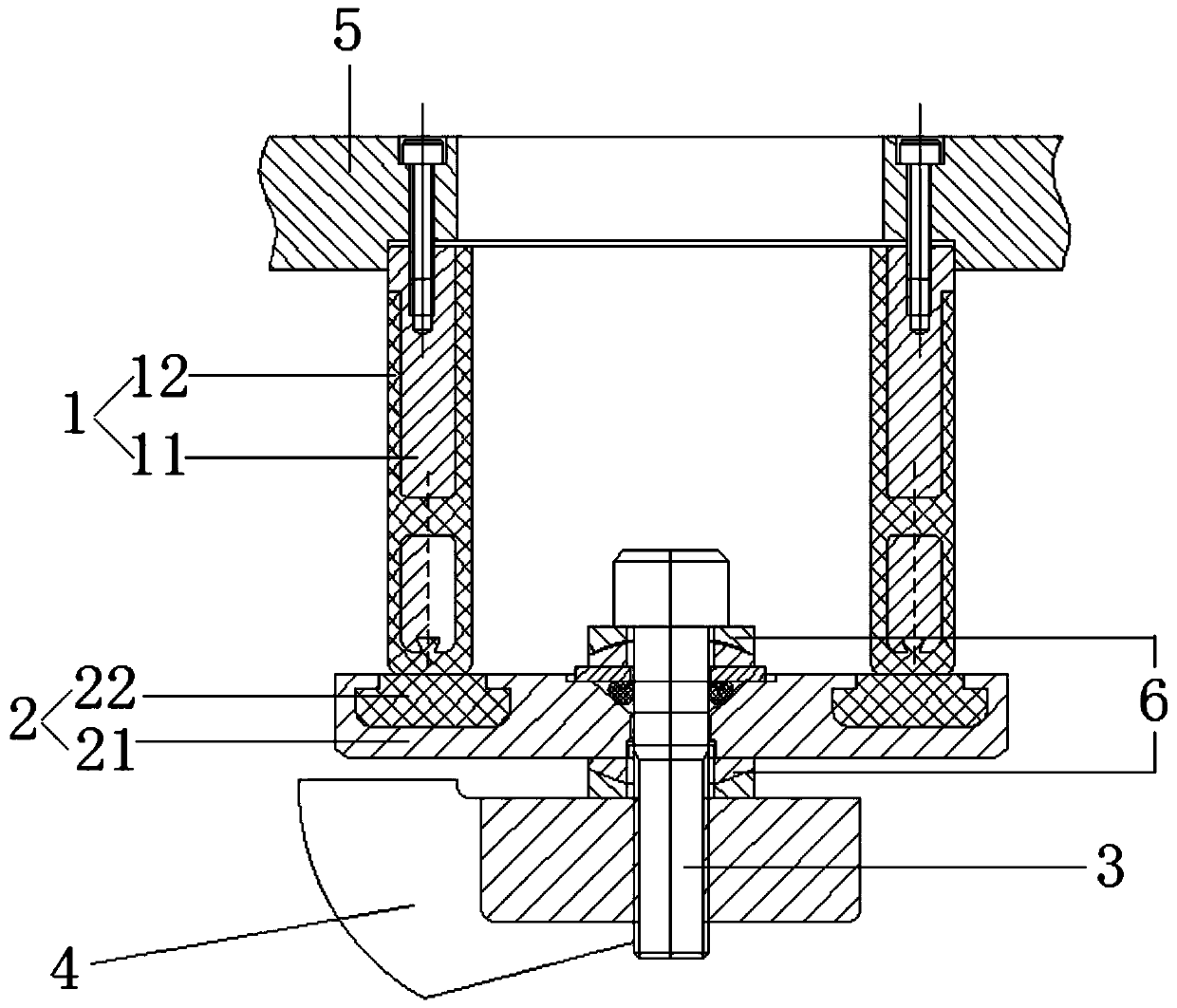
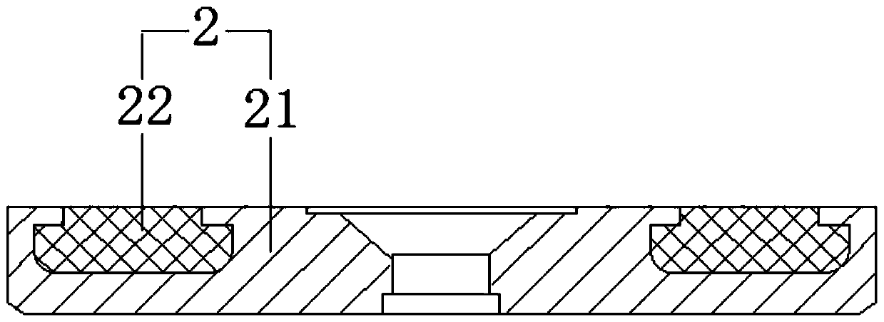
[0028] The embodiment of the present invention provides a rotary exhaust valve, as attached Figures 1 to 5 As shown, the rotary exhaust valve includes: a valve seat 1 and a valve cover 2, the val...


PUM


Abstract

The invention discloses a rotary exhaust valve comprising a valve seat and a valve cover. The valve seat comprises a metal cylinder body and a first cast rubber layer, the side wall of the metal cylinder body is provided with a plurality of perforated holes, the first cast rubber layer wraps the metal cylinder body, the first cast rubber layer comprises in-hole cast rubber, an inner cast rubber layer and an outer cast rubber layer, the perforated holes are filled with the in-hole cast rubber, and the in-hole cast rubber is connected with the inner cast rubber layer and the outer cast rubber layer; and the valve cover includes a cover body and a second cast rubber layer, an annular groove is formed in the position, corresponding to the valve seat, of the cover body, and the second cast rubber layer is located in the annular groove. According to the rotary exhaust valve, the perforated holes are formed in the metal cylinder, as for the first cast rubber layer, the inner casting rubber layer and the outer casting rubber layer are connected through the in-hole cast rubber, the implication performance can be strengthened, and falling is not prone to happening. The second cast rubber layer is located in the annular groove in the cover body, and extrusion deformation or crushing is not prone to happening. The first cast rubber layer and the second cast rubber layer are not prone to being detached or damaged, the rotary exhaust valve is low in failure rate, and the service life is long.

Description

technical field [0001] The invention relates to the technical field of blast furnace coal injection tank pressure relief equipment, in particular to a rotary exhaust valve. Background technique [0002] In blast furnace smelting, the coke production process is replaced by pulverized coal injection. Blast furnace pulverized coal injection system includes: upper dome valve, lock tank, rotary exhaust valve, lower dome valve, injection tank and balance valve. The upper dome valve is located on the top of the lock valve, the lower dome valve is located between the lock tank and the blow tank, the two ends of the balance valve are respectively connected with the lock tank and the blow tank, and the rotary exhaust valve is connected with the side wall of the lock tank , open when feeding in the lock tank. Closed when the inside of the lock tank enters the spray tank down. [0003] The rotary exhaust valve includes a valve cover and a valve seat. The valve cover is connected to t...

Claims


Application Information

Patent Timeline
Patent Type & Authority Applications(China)
IPC IPC(8): F16K1/36F16K1/42F16K1/20
CPCF16K1/20F16K1/36F16K1/42
Inventor 张守旗李京业王金刚桑子亮邹磊明张灿星
Owner SHANDONG IRON & STEEL CO LTD
Why Eureka
Try Eureka