
Detection circuit applied to piezoresistive sensor

A technology for detecting circuits and sensors, which is applied in the direction of transmitting sensing components, instruments, and measuring forces using electric/magnetic devices, can solve problems such as large experimental errors and errors, and achieve reduced equipment costs, high stability, and detection results. Stable and precise effects

Pending Publication Date: 2019-09-10
WUYI UNIV
View PDF0 Cites 0 Cited by
  • Summary
  • Abstract
  • Description
  • Claims
  • Application Information

AI Technical Summary

Problems solved by technology

At present, the traditional test method is to test the potential difference between the two ends of the piezoresistive sensor through the Wheatstone bridge to reflect the changes in the external test environment. This test method will bring large experimental errors, and most of the detected electrical signals show There are many unstable factors, and there are many common-mode signals with strong interference, which brings a lot of error to the experimental results.

Method used

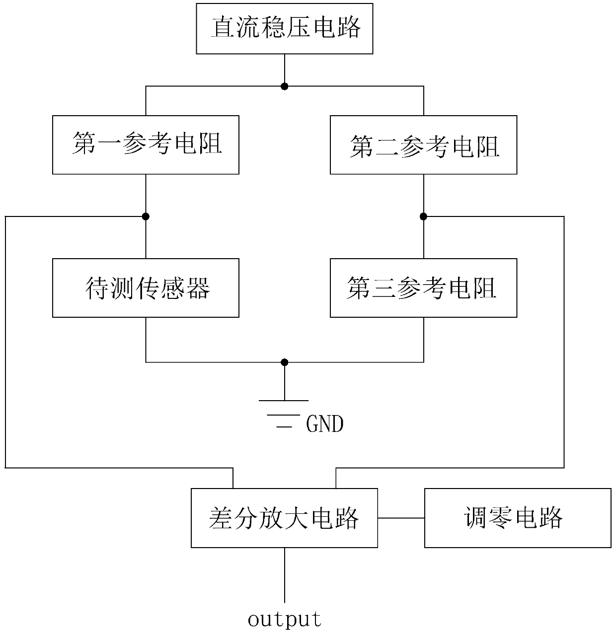
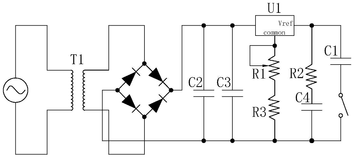
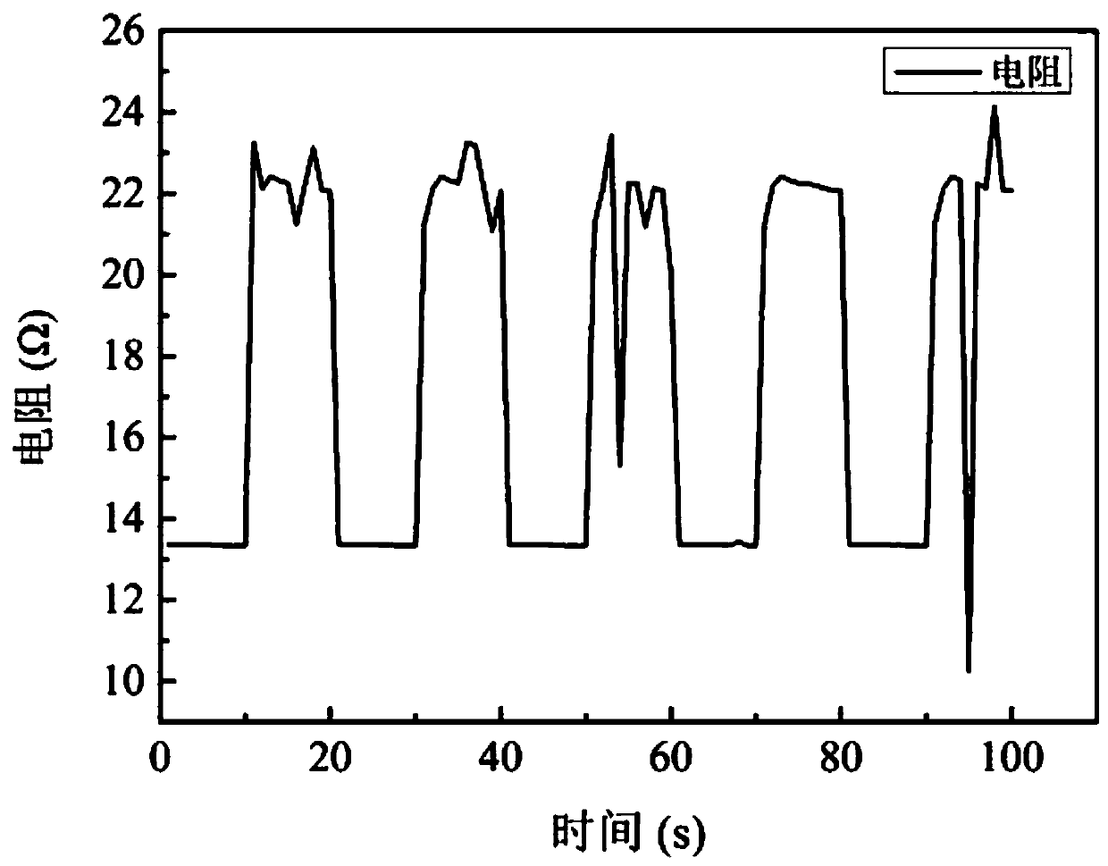

Image

  • Detection circuit applied to piezoresistive sensor
  • Detection circuit applied to piezoresistive sensor
  • Detection circuit applied to piezoresistive sensor

Examples


Embodiment Construction

[0018] This section will describe the specific embodiments of the present invention in detail. The preferred embodiments of the present invention are shown in the drawings. The function of the drawings is to supplement the description of the text part of the manual with graphics, so that people can intuitively and vividly understand the text. Each technical feature and overall technical solution of the invention cannot be understood as a limitation on the protection scope of the present invention.

[0019] In the description of the present invention, it should be understood that the orientation description involved, for example, the orientation or positional relationship indicated by up, down, front, back, left, right, etc., is based on the orientation or positional relationship shown in the drawings, and only In order to facilitate the description of the present invention and simplify the description, it does not indicate or imply that the pointed device or element must have a sp...


PUM

PropertyMeasurementUnit
First resistoraaaaaaaaaa
Second resistoraaaaaaaaaa

Abstract

The invention discloses a detection circuit applied to a piezoresistive sensor. The detection circuit comprises a DC voltage stabilizing circuit, a voltage dividing circuit, a differential amplifyingcircuit and a zero setting circuit, which are sequentially connected, wherein the voltage dividing circuit comprises a first branch and a second bracket connected in parallel with each other, the irstbranch is formed by connecting a first reference resistor and a serial end in series, the second branch is formed by connecting a second reference resistor and a third reference resistor in series, circuits are respectively led out from the first reference resistor and the serial end and between the second reference resistor and the third reference resistor to access the differential amplifying circuit, a potential difference under zero input is eliminated by using the zero setting circuit, meanwhile further smoothing processing is performed on the detection current in combination with the DCvoltage stabilizing circuit, so that the detection result of the piezoresistive sensor is more stable and accurate, meanwhile, the equipment cost of the circuit is also reduced, and the stability ishigher.

Description

Technical field [0001] The invention relates to a sensor-oriented detection circuit, in particular to a detection circuit applied to a piezoresistive sensor. Background technique [0002] The piezoresistive sensor changes some of the performance of the sensor itself by sensing the changes of external physical quantities, and these changes will be output as electrical signals through the conversion element. At present, the traditional test method is to test the potential difference between the two ends of the piezoresistive sensor through the Wheatstone bridge to reflect the changes of the external test environment. This test method will bring large experimental errors, and most of the detected electrical signals are present. There are many unstable factors and many common-mode signals with strong interference, which bring great errors to the experimental results. Summary of the invention [0003] In order to solve the above problems, the present invention provides a detection cir...

Claims


Application Information

Patent Timeline
IPC IPC(8): G01D5/16G01L1/20
CPCG01D5/16G01L1/20
Inventor 何鑫刘志豪沈耿哲张弛杨为家赵思柔陈柏桦
Owner WUYI UNIV
Learn More