New energy automobile battery cooler

A technology of new energy vehicles and coolers, applied in electric vehicles, secondary batteries, electrochemical generators, etc., can solve the problems of reducing the cooling effect, accelerating the flow rate of the coolant, and incomplete atomization of the coolant, so as to change the absorption Effects of thermal efficiency, increasing atomization time, and improving efficiency

Inactive Publication Date: 2019-09-10
钟家明
View PDF0 Cites 1 Cited by
  • Summary
  • Abstract
  • Description
  • Claims
  • Application Information

AI Technical Summary

Problems solved by technology

[0005] Aiming at the deficiencies of the prior art, the present invention provides a battery cooler for new energy vehicles, which is equipped with a baffle plate and a flow stop device, which can block the droplets in the mist coolant and guide them back into the coolant tank , Ensure that only mist coolant enters the evaporator to improve the cooling effect of the cooler, and the sliding adjustment mechanism can reduce the cross-sectional area of ​​the tapered hole to accelerate the flow rate of the coolant and increase the cooling rate, etc., which solves the common problem Car battery coolers tend to make the coolant atomized incompletely, reduce the cooling effect, cannot adjust the flow speed of the coolant, and cannot adjust the cooling speed according to actual needs

Method used


Image

  • New energy automobile battery cooler
  • New energy automobile battery cooler
  • New energy automobile battery cooler

Examples


Embodiment Construction

[0029] The technical solutions in the embodiments of the present invention will be clearly and completely described below in conjunction with the accompanying drawings in the embodiments of the present invention. Obviously, the described embodiments are only a part of the embodiments of the present invention, rather than all the embodiments. Based on the embodiments of the present invention, all other embodiments obtained by those of ordinary skill in the art without creative work shall fall within the protection scope of the present invention.

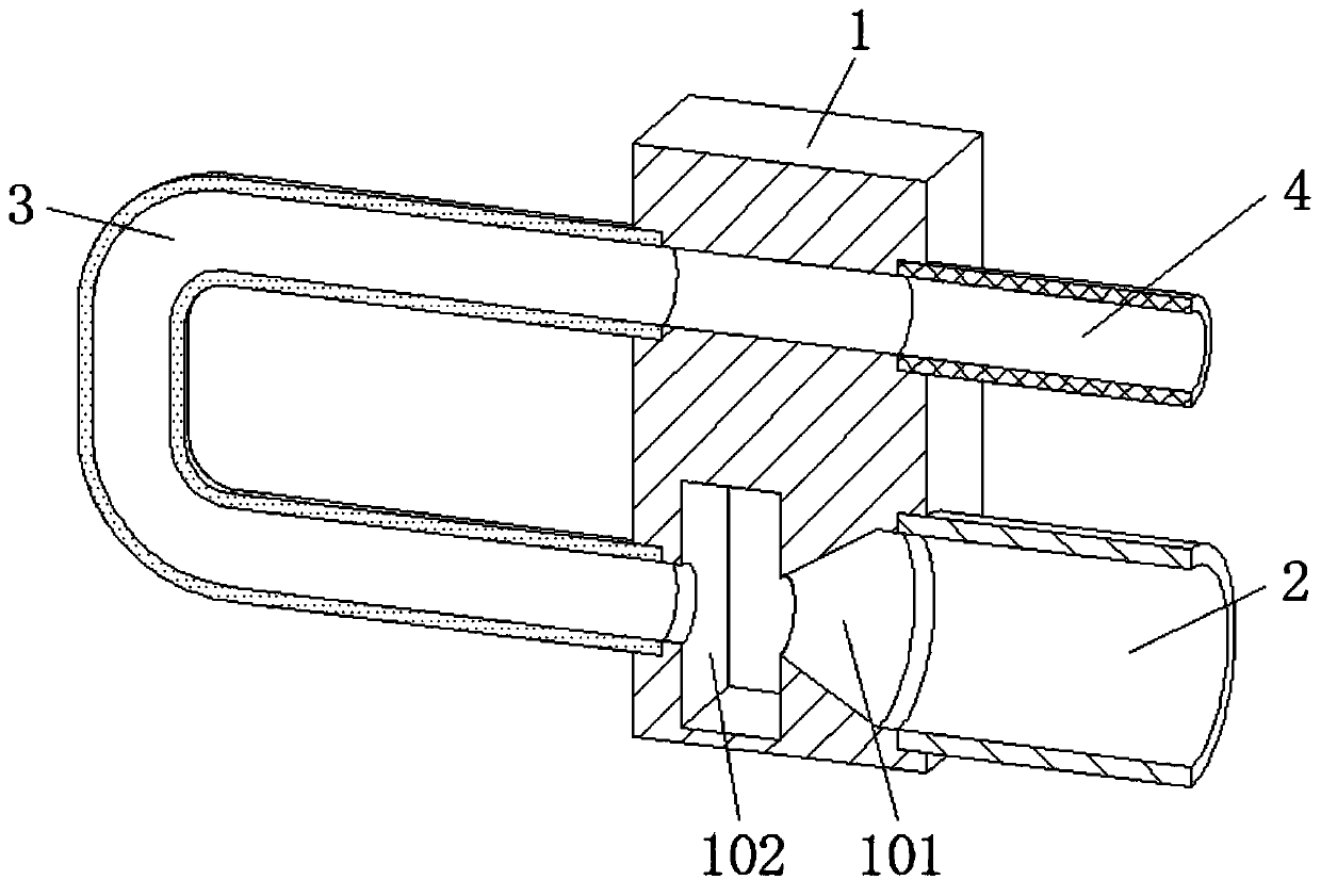
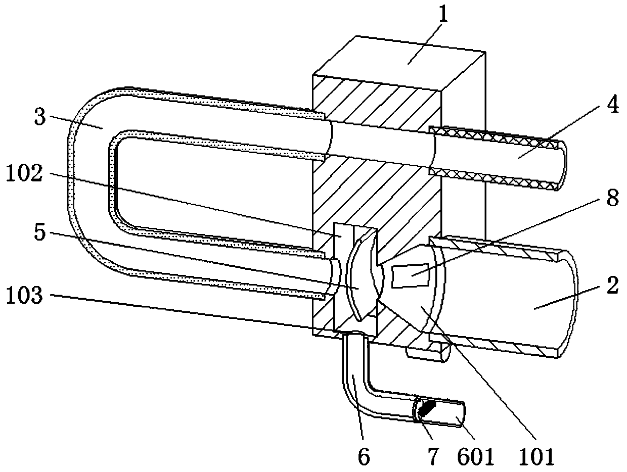
[0030] See Figure 2-7 , A new energy vehicle battery cooler, comprising a base 1, a tapered hole 101, a cavity 102, a liquid inlet tube 2, a heat exchange tube 3 and a liquid outlet tube 4, and the cavity 102 is fixed between the front and rear sides The baffle 5 is installed. The height of the baffle 5 is larger than the size of the opening of the tapered hole 101 to ensure effective blocking of misty coolant. The cross-sectional shape...


PUM


Abstract

The invention relates to the technical field of battery coolers, and discloses a new energy automobile battery cooler. The new energy automobile battery cooler comprises a base, a conical hole, a cavity, a liquid inlet pipe, a heat exchange pipe and a liquid outlet pipe; a flow baffle is fixedly mounted between the front side surface and the rear side surface of the interior of the cavity; a liquid discharge hole is formed in the bottom surface of the cavity; and a backflow pipe I is fixedly connected to the interior of the liquid discharge hole in a sleeving mode. According to the new energyautomobile battery cooler, cooling liquid enters the cavity after being atomized through the conical hole; on one hand, the fog-state cooling liquid impacts the flow baffle inside the cavity, liquid droplets of the cooling liquid which is not completely atomized are attached to the concave surface of the flow baffle and are accumulated inside the backflow pipe I, and when a certain amount of the liquid droplets is accumulated, the baffle is pressed to be opened, so that the cooling liquid flows back to a cooling liquid tank; and on the other hand, the fog-state cooling liquid is blocked by theflow baffle, so that a path of reaching the heat exchange pipe by the fog-state cooling liquid is prolonged, the atomizing time of the fog-state cooling liquid is further prolonged, the atomization of the cooling liquid is more sufficient, and the cooling efficiency is improved.

Description

Technical field [0001] The invention relates to the technical field of battery coolers, in particular to a new energy automobile battery cooler. Background technique [0002] A new energy vehicle battery cooler is a device used to cool the battery of a new energy vehicle to ensure that the vehicle battery is at a normal operating temperature. The vehicle battery cooler is generally composed of a heat exchanger, an expansion valve and an evaporator. [0003] The internal structure of common expansion valves is such as figure 1 As shown, it includes the base, the inlet pipe, the heat exchange pipe and the outlet pipe. The high-pressure and high-temperature coolant enters the base from the inside of the inlet pipe, and reaches the cavity after passing through the tapered hole. Effect, the cooling liquid is transformed into low-temperature and low-pressure mist cooling liquid inside the cavity, which is convenient for subsequent entry into the evaporator to evaporate into gaseous heat ...

Claims


Application Information

Patent Timeline
Patent Type & Authority Applications(China)
IPC IPC(8): H01M10/613H01M10/625H01M10/6568B60K1/00B60L58/26
CPCB60K1/00B60K2001/005B60L58/26H01M10/613H01M10/625H01M10/6568Y02E60/10Y02T10/70
Inventor 不公告发明人
Owner 钟家明
Why Eureka
Try Eureka