Method and device for flexible Ethernet device port binding, path establishment method and device

A device port and port binding technology, which is applied in multiplexing communication, time division multiplexing system, electrical components, etc., can solve blind binding, lack of signal type and capability release mechanism, and failure to perform normal multiplexing Use and solve problems such as FlexEclient signals to achieve the effect of ensuring successful establishment

Active Publication Date: 2022-05-20
ZTE CORP
View PDF8 Cites 0 Cited by
  • Summary
  • Abstract
  • Description
  • Claims
  • Application Information

AI Technical Summary

Problems solved by technology

The existing technology only releases the identification of a single port, and does not involve the release of related capabilities at the board level. It cannot clearly indicate the maximum number of Ethernet PHY interfaces that can be used to establish a FlexE group, and there is no specific internal board that can be used to establish a FlexE group. Therefore, when binding ports, the number of established FlexE groups exceeds the maximum number of FlexE groups that can be provided by the board, resulting in the bound port being unable to use normally
[0008] In addition, for a single board inside a FlexE device, it contains signals of two different protocol layers, one is the signal of the MAC layer where the FlexE client resides, the other is the signal of the physical layer where the FlexE group resides, and the signal presented by the FlexE device to the outside The port is actually an Ethernet PHYs port, and the FlexE client signal port is inside the FlexE device and is not visible to the outside, but in the actual process of establishing a connection, the FlexE client signal type supported by the device also needs to be considered, while the existing technology Due to the lack of a release mechanism for the signal types and capabilities supported by FlexE devices, it may not be able to multiplex and demultiplex FlexE client signals during path establishment.
[0009] Furthermore, 25Gb / s Ethernet signal is a newly standardized signal type in recent years. Its MAC layer processing method, physical layer processing method and interface processing method between the two layers are all similar to 10Gb / s Ethernet The signals are similar, which also causes most of the existing chips to support configurable 10Gb / s and 25Gb / s Ethernet signals, that is, the corresponding ports on the board can be configured as 10G ports or 25G ports as required. , and the existing technology does not have a relevant mechanism to announce whether the sending or receiving end has the ability to support signal switching, resulting in the control plane not being able to flexibly configure modules that support signal switching to perform different signal forwarding when calculating paths.
[0010] Based on the above reasons, at present, the parameter information of the board corresponding to the flexible Ethernet device port is not released on the public platform, which may lead to blindly binding ports during the port binding operation, and the number of bound ports may exceed the number of ports available for binding. The maximum number of ports; it is also possible that the number of port binding groups exceeds the maximum number of modules used to bind ports, resulting in the bound ports not being used normally; in addition, because there is no FlexE client supported by the flexible Ethernet device on the public platform The signal type information of the signal, whether it supports signal type switching, and the switchable signal type information may cause the control plane to fail to perform multiplexing and demultiplexing due to the inconsistency of the signal types supported by the flexible Ethernet device at the transceiver end when establishing a communication path. Multiplexing FlexE client signals

Method used


Image

  • Method and device for flexible Ethernet device port binding, path establishment method and device
  • Method and device for flexible Ethernet device port binding, path establishment method and device
  • Method and device for flexible Ethernet device port binding, path establishment method and device

Examples


Embodiment Construction

[0054] In order to understand the characteristics and technical contents of the embodiments of the present invention in more detail, the implementation of the embodiments of the present invention will be described in detail below in conjunction with the accompanying drawings. The attached drawings are only for reference and description, and are not intended to limit the embodiments of the present invention.

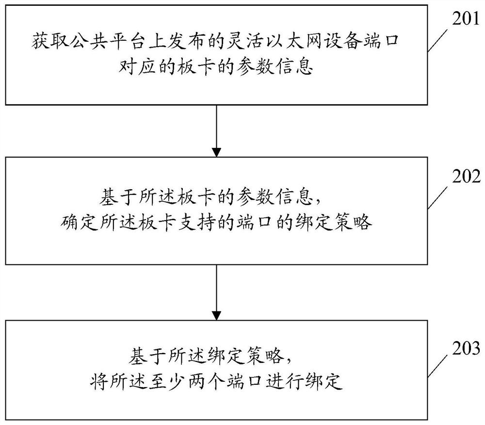
[0055] figure 2 It is a schematic flow diagram of the flexible Ethernet device port binding method in the embodiment of the present invention, as figure 2 As shown, the flexible Ethernet device port binding method includes the following steps:

[0056] Step 201: Obtain the parameter information of the board corresponding to the port of the flexible Ethernet device released on the public platform.

[0057] The operator obtains the parameter information of the board corresponding to the port of the FlexE device to be bound from the public platform.

[0058] In the embod...


PUM


Abstract

The invention discloses a method and device for binding a port of a flexible Ethernet device. The method includes: obtaining parameter information of a board corresponding to a port of a flexible Ethernet device released on a public platform; , determining a binding policy of ports supported by the board; and binding the at least two ports based on the binding policy. The present invention also discloses a method and device for establishing a flexible Ethernet path. The method includes: obtaining the signal type information of the flexible Ethernet client signals respectively supported by the flexible Ethernet devices at the sending end and the receiving end released on the public platform ; Based on the signal type information, determine whether the types of flexible Ethernet client signals supported by the flexible Ethernet devices at the sending end and the receiving end are the same; when determining that the types of the flexible Ethernet client signals are the same, establish the Communication path between sender and receiver.

Description

technical field [0001] The invention relates to control plane technology, in particular to a method and device for binding ports of flexible Ethernet equipment and a method and device for establishing flexible Ethernet paths. Background technique [0002] Flexible Ethernet (FlexE, Flex Ethernet) is a new emerging link transmission technology, which provides a general mechanism to support various existing Ethernet media access control (MAC, Media access control) signal rates, these Ethernet The network MAC rate can not be matched to any existing Ethernet physical layer (PHY, Physical Layer) rate, including the set of MAC signals that can be bonded to a higher rate than the Ethernet physical layer rate, and those sub-rates or channelized The obtained MAC signal is lower than the Ethernet physical layer rate. Specifically, the capabilities supported by Flexible Ethernet are as follows: [0003] 1. Bonding: For example, it supports bonding two 100G physical layer channels to c...

Claims


Application Information

Patent Timeline
Patent Type & Authority Patents(China)
IPC IPC(8): H04L49/253
CPCH04L49/253H04J2203/0085H04J3/1658
Inventor 王其磊
Owner ZTE CORP
Why Eureka
Try Eureka