
Solid-liquid grinding and mixing device for chemical industry

A mixing device and chemical technology, applied in the field of chemical solid-liquid grinding and mixing devices, can solve the problems of uneven mixing and low efficiency, and achieve the effects of improving efficiency and effect, facilitating grinding and avoiding interference.

Inactive Publication Date: 2019-09-13
戴韵
View PDF0 Cites 4 Cited by
  • Summary
  • Abstract
  • Description
  • Claims
  • Application Information

AI Technical Summary

Problems solved by technology

[0003] In the process of chemical processing, it is necessary to mix solid and liquid raw materials. The traditional mixing equipment uses a general stirring machine with a stirring structure for mixing. The mixing is uneven and inefficient. This application provides a chemical solid-liquid grinding The mixing device makes the solid and liquid raw materials dissolve and mix evenly and efficiently

Method used


Image

  • Solid-liquid grinding and mixing device for chemical industry
  • Solid-liquid grinding and mixing device for chemical industry
  • Solid-liquid grinding and mixing device for chemical industry

Examples


Embodiment 1

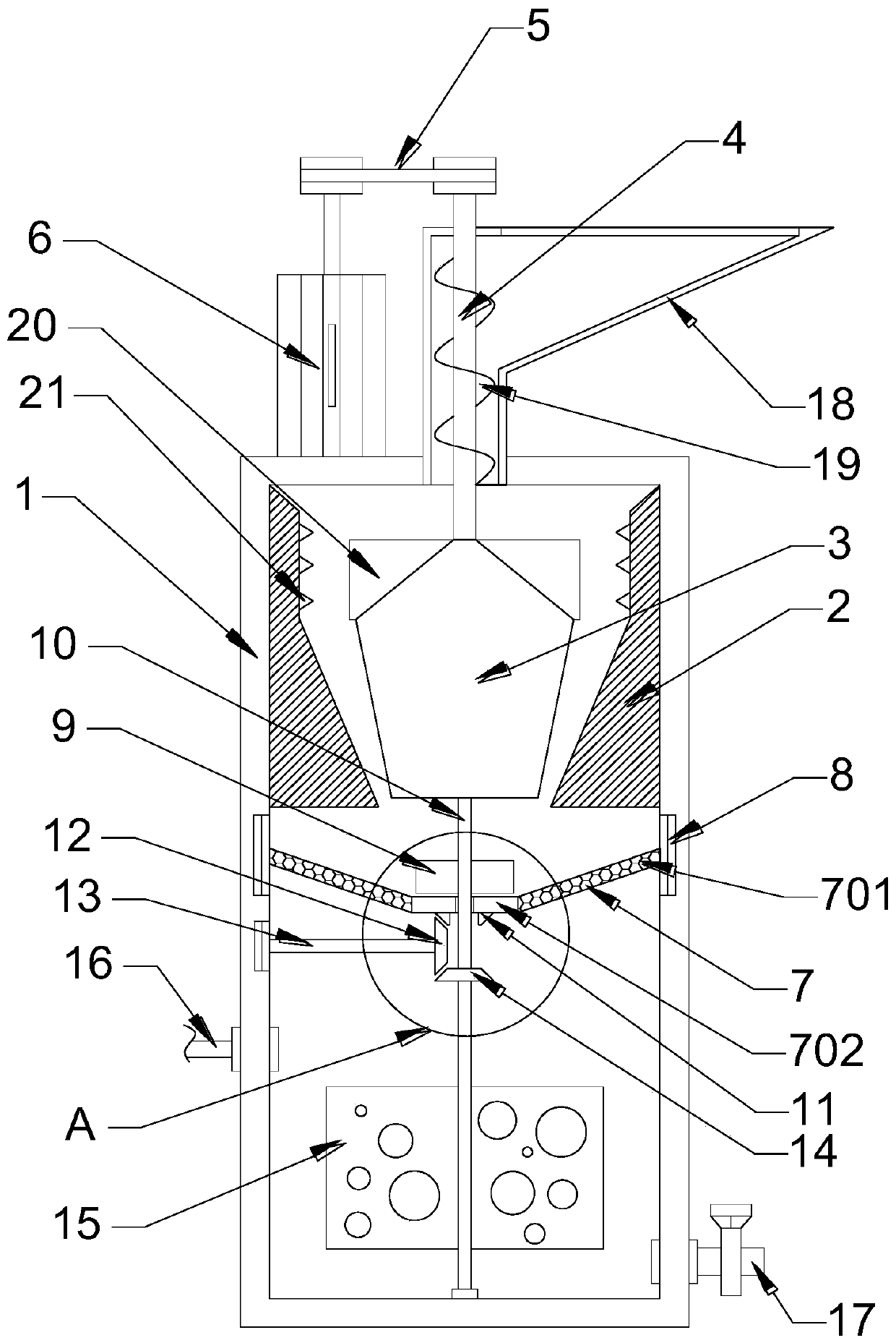
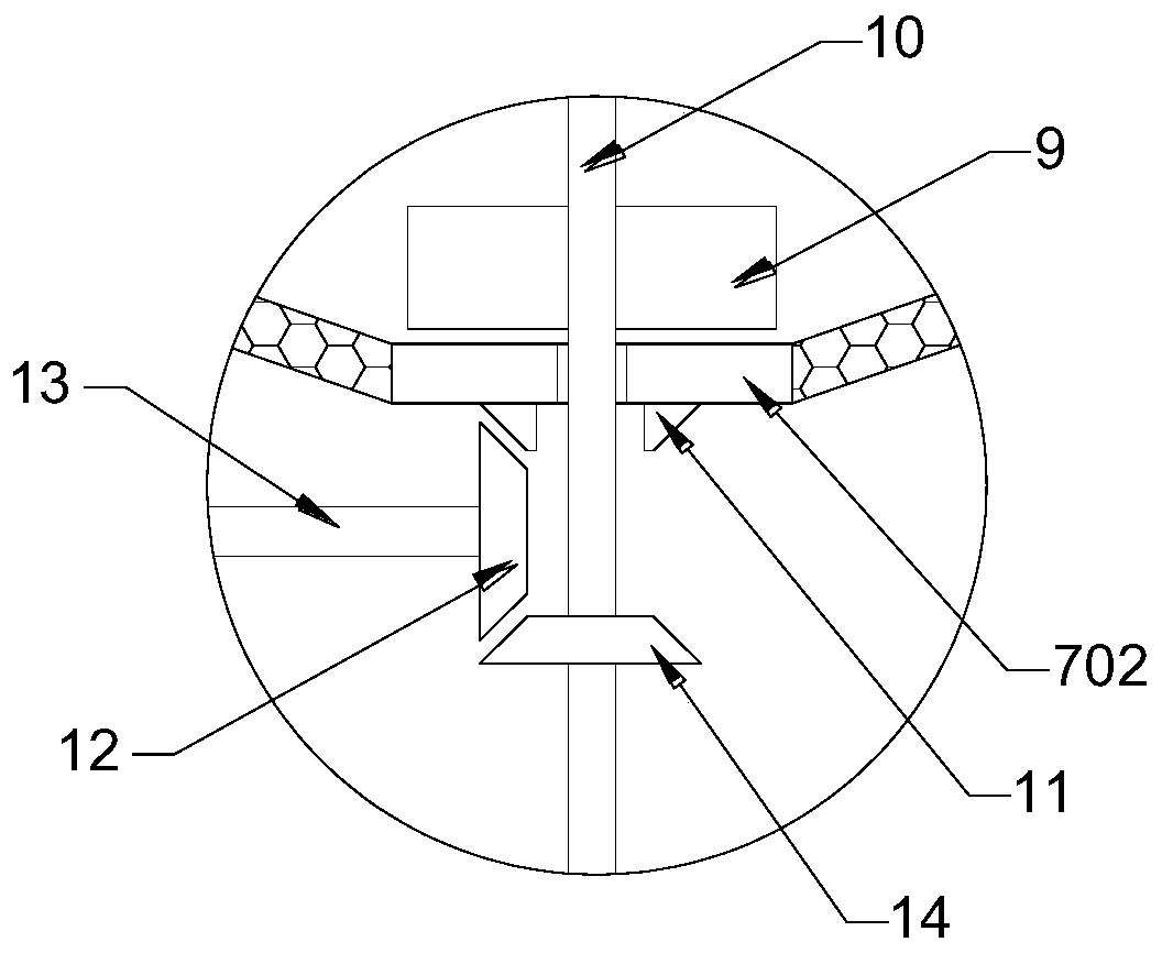
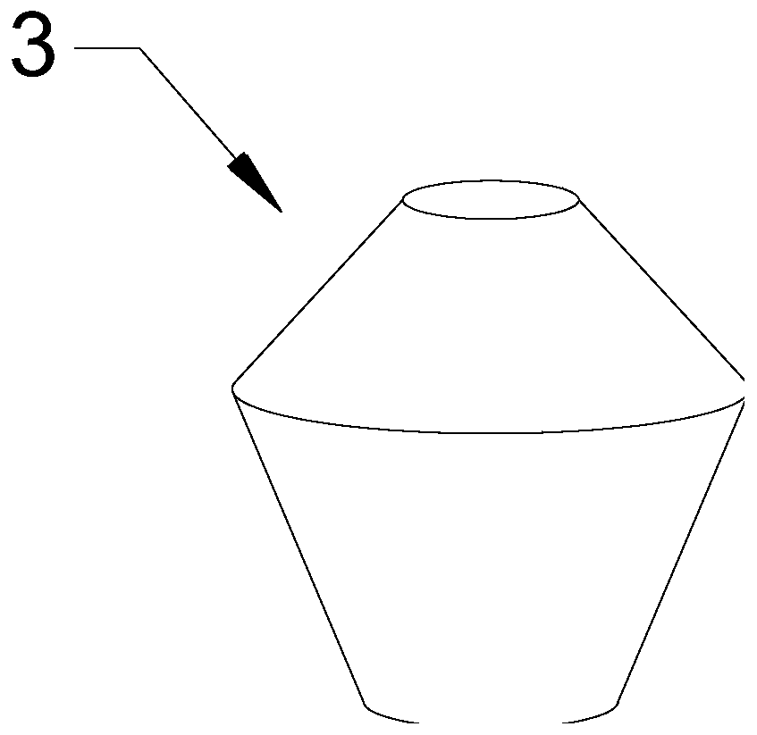
[0022] see Figure 1-4 , in an embodiment of the present invention, a solid-liquid grinding and mixing device for chemical industry, comprising a box body 1, a grinding shell 2 and a grinding hammer 3; the inner wall of the box body 1 is fixedly connected with a grinding shell 2, and the grinding shell 2 is nested with Grinding hammer 3, the upper end of grinding hammer 3 is fixedly connected with driving shaft 4, driving shaft 4 is connected with grinding motor 6 through transmission belt 5, grinding motor 6 is electrically connected with external power supply, grinding motor 6 drives grinding hammer 3 to rotate, grinding hammer 3 Cooperate with the grinding shell 2 to grind the solid raw materials entering the box 1, refine the solid raw material particles, facilitate the mixing and dissolving of raw materials and commercial raw materials, and improve the dissolution and mixing efficiency.

[0023] A dispersing cylinder 7 is provided below the grinding hammer 3, and the oute...

Embodiment 2

[0027] The difference between this embodiment and Embodiment 1 is that a feeding hopper 18 is communicated with the top of the box body 1, and a screw feeding blade 19 is arranged in the feeding hopper 18, and the screw feeding blade 19 is fixedly connected with the drive shaft 4 to keep feeding The speed is very constant to ensure the effect of dissolving and mixing; the grinding hammer 3 is fixedly connected with vertical plates 20 distributed in a circle, and the vertical plates 20 rotate with the grinding hammer 3 to scatter the plate agglomerates in the solid raw materials to the outside , The inner wall of the grinding shell 2 is provided with impact teeth 21 distributed in a circle, and the plate agglomerates collide with the impact teeth to break, which is convenient for subsequent grinding.


PUM


Abstract

The invention discloses a solid-liquid grinding and mixing device for chemical industry. The device comprises a box grinding hammer, below which a dispersing cylinder is arranged. The circumferentialsurface of the dispersing cylinder is provided with uniformly-distributed sieve apertures. A bearing plate is disposed below the dispersing cylinder, and the bearing plate is abutted against a throwing plate. Through the dispersing cylinder having sieve apertures on the circumferential surface and with the bearing plate arranged at the bottom thereof and through the throwing plate, solid particlesobtained after grinding and crushing are uniformly paved on the dispersing cylinder and uniform fall down through the sieve apertures. Then, the solid particles and liquid raw materials are uniformlymixed, and the mixing efficiency and effect are improved. By arranging circumferentially-distributed vertical plates on the grinding hammer and arranging impact tooth on the inner wall of a grindingshell, agglomerates in the solid raw materials are pretreated, which is convenient for subsequent grinding and avoids the interference of the agglomerates with the grinding work.

Description

technical field [0001] The invention relates to the field of chemical processing equipment, in particular to a solid-liquid grinding and mixing device for chemical industry. Background technique [0002] Chemical equipment is a part of chemical machinery. Chemical machinery consists of two parts. One is chemical machinery, which mainly refers to equipment such as fans, compressors, and various pumps for fluid transportation. The main components are moving machinery, generally called chemical engineering. machine. The second is that chemical equipment mainly refers to machinery whose components are static, such as separation equipment such as towers, containers, reactor equipment, etc., sometimes also called non-standard equipment. [0003] In the process of chemical processing, it is necessary to mix solid and liquid raw materials. The traditional mixing equipment uses a general stirring machine with a stirring structure for mixing. The mixing is uneven and inefficient. Thi...

Claims


Application Information

Patent Timeline
IPC IPC(8): B01F13/10
CPCB01F33/8305B01F33/83613
Inventor 戴韵
Owner 戴韵
Learn More