
Flat wire unwinding machine

A technology of pay-off machine and flat wire, which is applied in the direction of conveying filamentous materials, thin material processing, transportation and packaging, etc., which can solve the problems of unfavorable production personnel for installation, replacement of wire barrels, damage to the surface protective layer of wire materials, and large space occupation and other issues to achieve the effect of shortening equipment downtime, ensuring sustainability and improving production efficiency

Pending Publication Date: 2019-09-13
苏州创易技研股份有限公司
View PDF0 Cites 4 Cited by
  • Summary
  • Abstract
  • Description
  • Claims
  • Application Information

AI Technical Summary

Problems solved by technology

The over-discharge state will cause the wire that was originally tightly wound on the wire barrel to be excessively loosened, and there is a probability that some flat wires that are not very thick are easy to entangle, twist or even buckle.
[0005] In order to avoid the above-mentioned setting-out errors, a motor and a gear transmission mechanism can also be added to the above-mentioned mechanism, but no matter how the structure is arranged, the space occupied by the whole mechanism is relatively large, and the equipment cost is increased.
In addition, such a structure is not conducive to the operation of production personnel to install and replace the wire spool, and it is easier to bump and damage the protective layer on the surface of the wire

Method used


Image

  • Flat wire unwinding machine
  • Flat wire unwinding machine
  • Flat wire unwinding machine

Examples


Embodiment

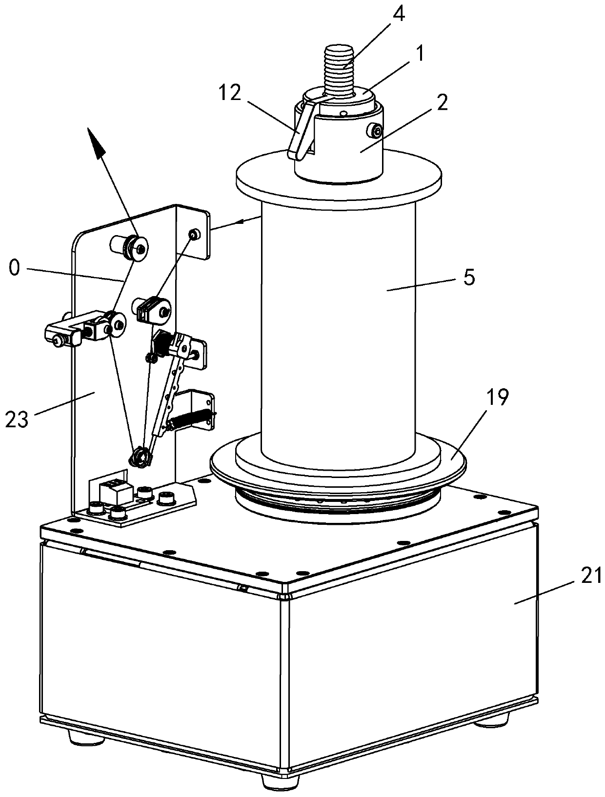
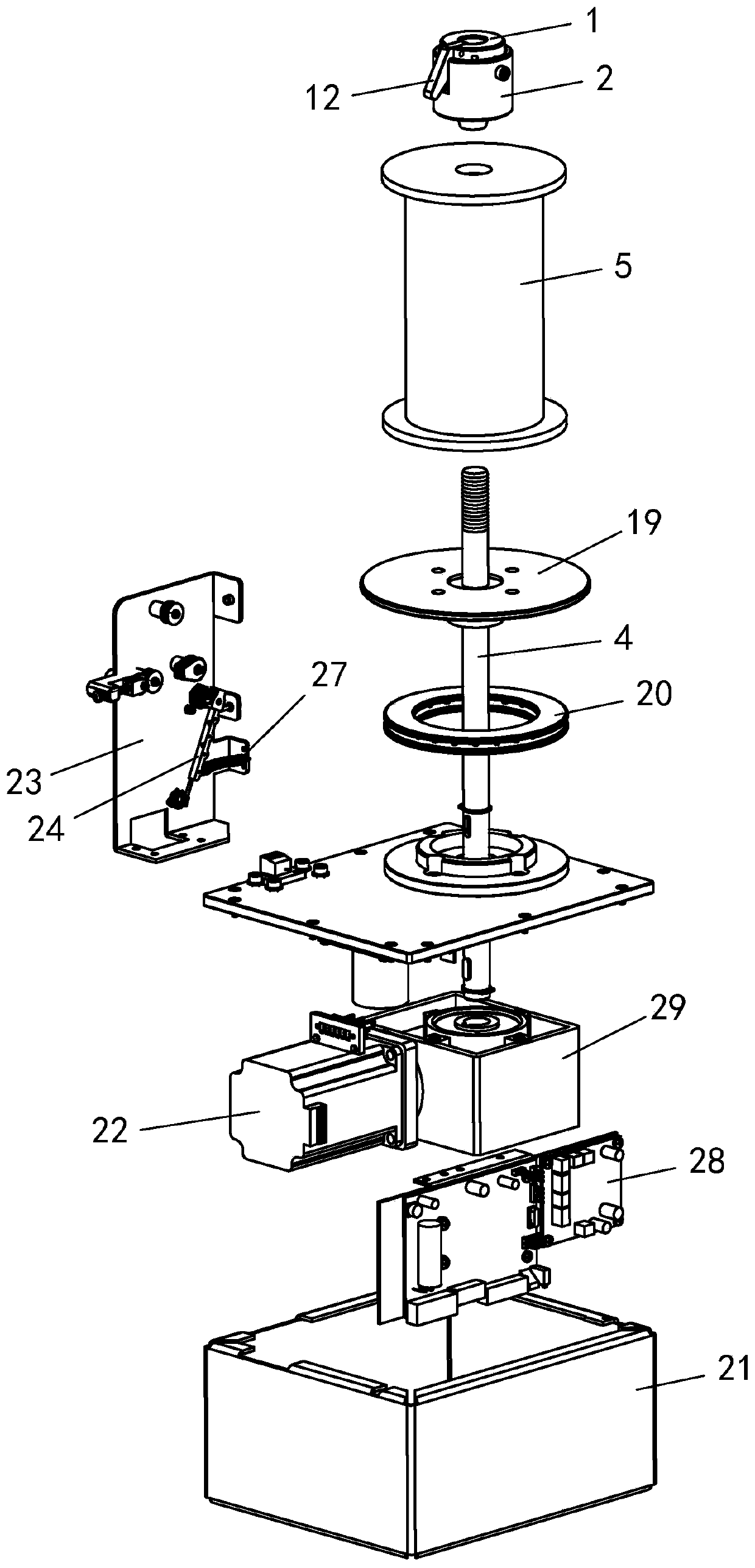
[0058] Example: see attached Figure 1~14 As shown, a flat wire pay-off machine includes a pay-off unit and a tension control unit.

[0059] Wherein, the pay-off unit includes a wire barrel quick disassembly structure and a wire barrel positioning structure.

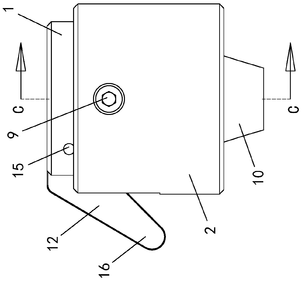
[0060] Such as Figure 3~10 As shown, the quick assembly and disassembly structure of the bobbin includes a pressing block 1 and a guide pressing cover 2 .

[0061] The middle part of the pressing block 1 is provided with a through hole 3 along the up and down direction, and the through hole 3 is used for the line barrel positioning shaft 4 of the pay-off machine to pass through.

[0062] A positioning hole 6 is arranged axially in the wire cylinder 5, and the radial width of the positioning hole 6 is greater than or equal to the radial width of the wire cylinder positioning shaft 4; when the wire cylinder 5 is installed, the wire cylinder 5 passes through the The positioning hole 6 is sleeved on the spool positioning...


PUM


Abstract

The invention discloses a flat wire unwinding machine. The flat wire unwinding machine comprises a wire unwinding unit and a tension control unit, wherein the wire unwinding unit comprises a bobbin quick disassembling and assembling structure and a bobbin positioning structure; the bobbin quick disassembling and assembling structure comprises a compressing block and a guide compressing cover; thecompressing block is in sliding fit with the guide compressing cover in the vertical wire unwinding direction; a taper-shaped positioning block is arranged at the bottom of the guide compressing coverand extends into a positioning hole of the bobbin to compress the bobbin; the compressing block is in elastic fit with the guide compressing cover through a first elastic part; a locking button is arranged on the compressing block and retains locking a bobbin positioning shaft through a second elastic part; the bobbin positioning structure comprises a plane supporting plate, a plane bearing and the bobbin positioning shaft; the plane supporting plate is rotatably arranged on a machine frame through the plane bearing; the bobbin positioning shaft is driven by a motor to rotate; the tension control unit corresponds to the wire unwinding side of the bobbin and comprises a base plate, a tension rod and a guide wheel; one end of the tension rod rotates relative to the base plate, and the otherend of the tension rod is provided with a wire unwinding wheel; and the tension rod is connected with a tension spring. The machine is capable of rapidly assembling and disassembling the bobbin conveniently, small in size, practical and reliable.

Description

technical field [0001] The invention relates to a wire pay-off device, in particular to a wire pay-off machine for square flat wires. Background technique [0002] Due to the high density of products wound with square flat wire, and the electrical parameters are better than those wound with round wire, it gradually has a tendency to be widely used. Because of its unique cross-sectional shape, the square flat wire cannot be drawn out of the wire barrel directly like the round wire, and must be released along the direction of the square flat wire, otherwise it is easy to twist and cause a pay-off error. [0003] The conventional pay-off method cannot meet the pay-off requirements of the square flat wire. This is because the conventional pay-off is in the form of drawing wire. In the drawing-out method, the wire barrel must be placed horizontally and installed On a mechanism similar to a roller, it is convenient for the spool to roll and pay off. However, such a structure is ...

Claims


Application Information

Patent Timeline
Patent Type & Authority Applications(China)
IPC IPC(8): B65H59/38B65H49/36B65H49/28B65H63/032
CPCB65H59/387B65H49/36B65H49/28B65H63/032B65H2701/35
Inventor 倪锦程
Owner 苏州创易技研股份有限公司
Learn More