A New Type of Load Holding Valve

A load holding valve, a new type of technology, applied in the field of hydraulic valves, can solve the problems of difficult control of orifice size tolerance, high requirements for oil cleanliness, high machining accuracy, etc., to achieve good self-centering effect and clean oil Low requirement for high pressure and good sealing effect

Active Publication Date: 2020-04-07
徐州阿马凯液压技术有限公司
View PDF11 Cites 0 Cited by
  • Summary
  • Abstract
  • Description
  • Claims
  • Application Information

AI Technical Summary

Problems solved by technology

[0005] 1. The main check valve needs to process the throttle hole; in the actual processing technology, this throttle hole is not easy to process, and the size tolerance of the throttle hole is difficult to control, and the processing accuracy is very high;
[0006] 2. When the oil chamber returns oil, part of the oil in the orifice leaks into the oil tank from the orifice, which affects the regeneration amount in the regeneration system;
[0007] 3. The orifice is easy to block and requires high oil cleanliness

Method used


Image

  • A New Type of Load Holding Valve
  • A New Type of Load Holding Valve
  • A New Type of Load Holding Valve

Examples


Embodiment Construction

[0032] The following is a specific embodiment of the present invention, and the present invention will be further described in conjunction with the accompanying drawings.

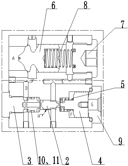
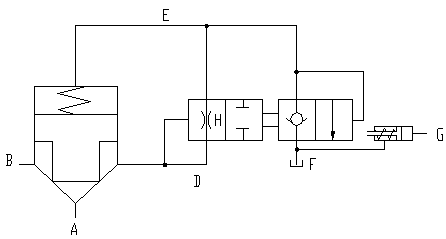
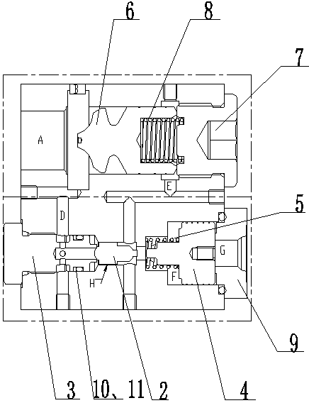
[0033] Such as figure 1 and figure 2 As shown in Fig. 1, a new type of load-holding valve, the valve body is provided with through step-type valve core installation holes I and valve core installation holes II, and the valve core installation holes I and valve core installation holes II are arranged in parallel. The spool installation hole Ⅰ is used to install the one-way valve part, and the spool installation hole Ⅱ is used to install the pilot control part.

[0034] The one-way valve core 6 is installed in the valve core installation hole I, and the spring chamber at the right end of the one-way valve core 6 is provided with a spring I8. A screw plug 7 is installed at the right end of the spool mounting hole I, and the spring I8 is placed between the one-way valve core 6 and the screw plug 7 . In orde...


PUM


Abstract

The invention discloses a novel load holding valve, and belongs to the technical field of hydraulic valves. A valve core mounting hole I and a valve core mounting hole II are formed in a valve body; aone-way valve core is mounted in the valve core mounting hole I; a spring I is arranged in a spring cavity in the right end of the one-way valve core; a plug, a cone valve core and an ejector rod aresequentially mounted in the valve core mounting hole II from left to right; the cone valve core is mounted in the valve core mounting hole II in a sliding manner; a gap H is formed between the circumferential surface of the cone valve core and the inner wall of the valve core mounting hole II; a matched sealing structure is formed between the left end of the cone valve core and an oil channel D of the plug; a matched sealing structure is arranged between the right end of the cone valve core and the inner step of the valve core mounting hole II; and a spring II is arranged in a spring cavity in the left end of the ejector rod. The novel load holding valve is simple in structure, the processing technology is convenient, when a load is held, only two valve cone surfaces form a sealing zone,the leakage rate is small, a throttle formed between the cone valve core and the valve core mounting hole II is a clearance throttle, the possibility of blocking is low, and the requirement on the cleanness of oil is relatively low.

Description

technical field [0001] The invention relates to a hydraulic valve, in particular to a novel load holding valve. Background technique [0002] The hydraulic excavator system has strict requirements on the settlement of the boom and the stick; therefore, in the hydraulic system, in order to ensure the settlement of the boom and the stick, a load holding device is added to the control valve, but due to the existing load The processing technology required by the holding device is complex, and the dimensional accuracy of the parts is high, which has high requirements for the accuracy of the processing equipment and the proficiency of the personnel. [0003] For example, a load holding valve (CN104763822A) published by a Chinese patent includes a first valve body, a first valve core, a first elastic member, a second valve body, a second valve core and a second elastic member. A valve body is provided with a first oil inlet, a first oil outlet and an accommodating chamber, the fir...

Claims


Application Information

Patent Timeline
Patent Type & Authority Patents(China)
IPC IPC(8): F15B13/02E02F9/22
CPCE02F9/2267F15B13/02
Inventor 吕德滨胡建军景军清戚振红徐明王宗勇孙坚
Owner 徐州阿马凯液压技术有限公司
Why Eureka
Try Eureka