Road energy collecting device

A technology for collecting device and road energy, applied in electromechanical devices, transmission devices, gear transmission devices, etc., can solve problems such as bumps and achieve high efficiency

Pending Publication Date: 2019-09-13
SOUTHWEST JIAOTONG UNIV
View PDF8 Cites 2 Cited by
  • Summary
  • Abstract
  • Description
  • Claims
  • Application Information

AI Technical Summary

Problems solved by technology

[0005] The purpose of the present invention is to provide a road energy harvesting device, which can effectively solve the problem that automobiles produce bumps through traditional road energy harvesting devices

Method used


Image

  • Road energy collecting device
  • Road energy collecting device
  • Road energy collecting device

Examples


Embodiment Construction

[0019] The present invention will be described in further detail below in conjunction with the accompanying drawings and specific embodiments.

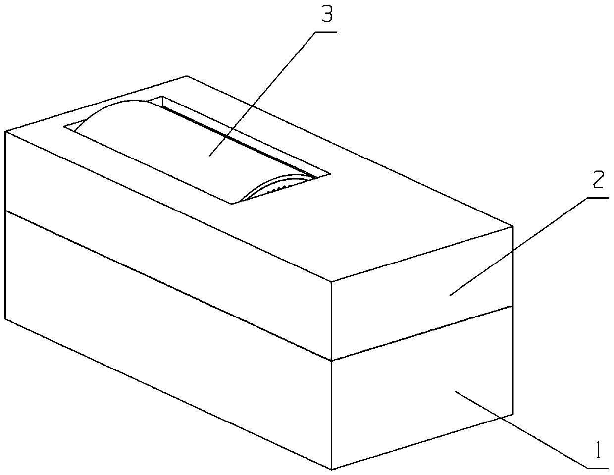
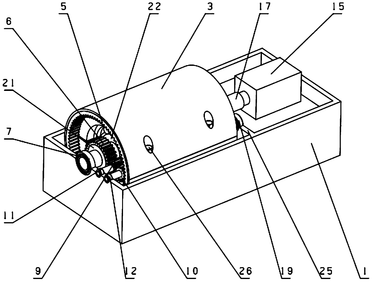
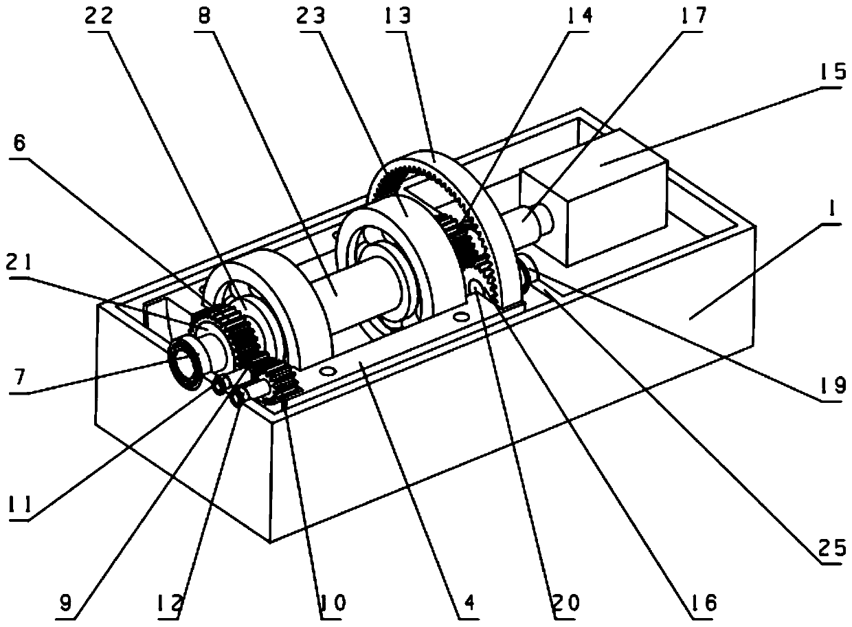
[0020] see Figure 1 ~ Figure 4 , the road energy harvesting device includes a split box body composed of an upper box body 2 and a lower box body 1, a vertical plate 25 is provided on the right side of the split box body, and a split horizontal box body is provided in the left box body. The split-type horizontal drum includes a drum upper part 3 and a drum lower part 4, which are fixed by bolts 26. It is characterized in that: the inner walls of the left and right ends of the split-type horizontal drum are respectively provided with left internal gears 5, The right internal gear 13; the upper surface of the upper box body 2 is provided with a rectangular hole, the top of the horizontal roller is located in the rectangular hole and is flush with the upper surface of the upper box body 2; the left end of the main drive shaft 8 passes t...


PUM


Abstract

The invention provides a road energy collecting device and relates to the technical field of design of energy transition devices. A left internal gear and a right internal gear are respectively arranged on the inner walls of two ends of a split horizontal roller; the left end of a main driving shaft is fixed with a left side vertical plate of a split box body through a left small angle contact ball bearing; an inner ring of the left small angle contact ball bearing is in interference fit with the main driving shaft; the right end of the main driving shaft is coupled with an input shaft of a power generator through a coupling; the main driving shaft on the inner side of the left small angle contact ball bearing is provided with a left spur gear meshed with a small planetary gear I; the small planetary gear I is meshed with a small planetary gear II with a half shaft; a shaft of the small planetary gear II is fixed with the left side vertical plate of the box body through a small deep groove ball bearing II; the small planetary gear II is meshed with the left internal gear; the main driving shaft on the inner side of the left spur gear is provided with a left large small contact ballbearing; an outer ring of the left large small contact ball bearing is fixed with the inner wall of the left side of the horizontal roller; a driving structure on the right side of the horizontal roller is similar to that on the left side of the horizontal roller. The road energy collecting device is used for collecting road energy.

Description

technical field [0001] The invention relates to the technical field of energy conversion device design. Background technique [0002] In recent years, the problems of energy shortage and environmental pollution have attracted widespread attention. The development and utilization of clean energy such as solar energy and wind energy has drawn increasing attention from many countries. Road energy harvesting is a new type of clean energy technology with development potential. It can collect part of the kinetic energy of vehicles passing by and convert it into electrical energy without affecting the normal driving of cars. Road energy harvesting technology can be used for power supply of roadside equipment such as monitoring, sensors, etc., so as to effectively save electric energy and avoid power loss and construction costs of long-distance power transmission. [0003] According to the search, there are related road energy collection devices, such as the Chinese invention pate...

Claims


Application Information

Patent Timeline
Patent Type & Authority Applications(China)
IPC IPC(8): F16H1/32F16H57/08H02K7/18H02K7/116
CPCF16H1/32F16H57/082H02K7/1861H02K7/116F16H2001/327F16H2001/324
Inventor 张祖涛孙梦蝶王伟张天明罗大兵潘亚嘉
Owner SOUTHWEST JIAOTONG UNIV
Why Eureka
Try Eureka