
Substrate processing apparatus that mechanically controls plasma density

A substrate processing device and plasma technology, applied in discharge tubes, electrical components, circuits, etc., can solve problems such as inability to effectively control plasma P density, faster replacement cycle, and inability to effectively control plasma density

Active Publication Date: 2019-09-13
GIGALANE CO LTD
View PDF9 Cites 1 Cited by
  • Summary
  • Abstract
  • Description
  • Claims
  • Application Information

AI Technical Summary

Problems solved by technology

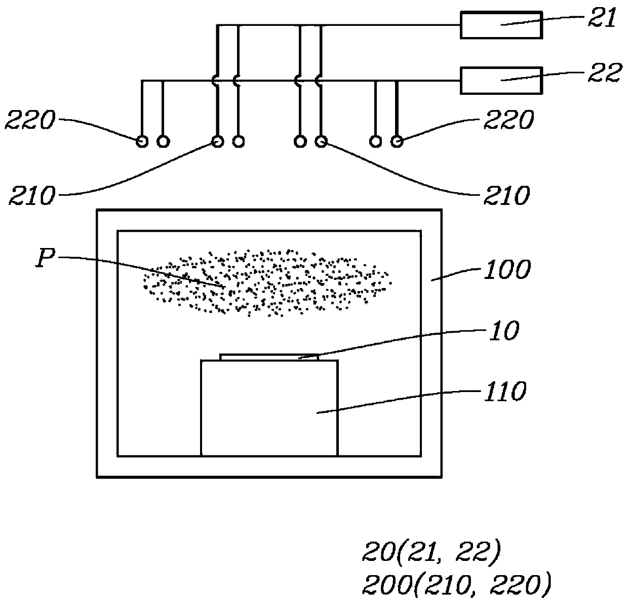
[0011] However, there is a problem that the high-frequency waves are affected by many environmental factors during the supply from the high-frequency power supply unit 20 to the antenna coil 200. Therefore, the high-frequency waves radiated from the antenna coil 200 cannot be effectively controlled as expected, and as a result, the plasma cannot be effectively controlled. P density
[0012] In addition, there is a problem that, in order to control high-frequency power, a plurality of electrical / electronic components are added, which increases management items, thereby making the replacement cycle faster
[0018] There is the same problem as the antenna coil 200 problem described above: the high-frequency waves radiated from the inner antenna coil 210 and the outer antenna coil 220 cannot be effectively controlled as expected, and as a result, the plasma density cannot be effectively controlled.
[0019] In addition, there is a problem that in order to separately control the high-frequency power supplied to the inner antenna coil 210 and the outer antenna coil 220, a plurality of electric / electronic configurations including the first high-frequency power supply unit 21 and the second high-frequency power supply unit 22 are added, Allows for a further increase in managed items, resulting in faster replacement cycles

Method used


Image

  • Substrate processing apparatus that mechanically controls plasma density
  • Substrate processing apparatus that mechanically controls plasma density
  • Substrate processing apparatus that mechanically controls plasma density

Examples


Embodiment Construction

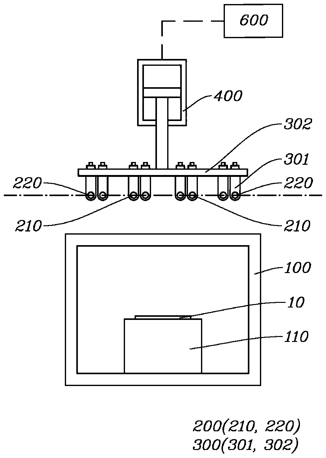
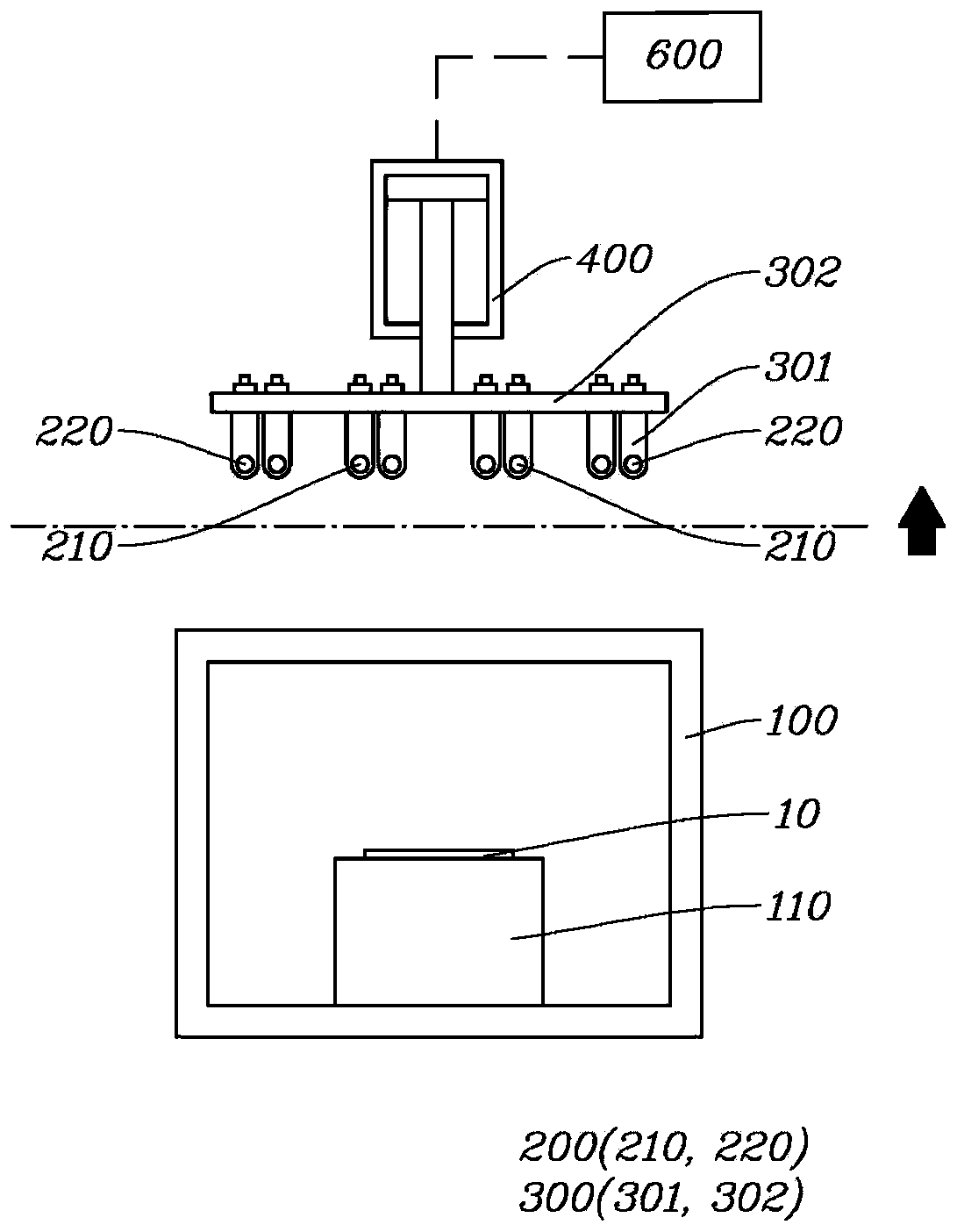
[0083] Such as Figure 2 to Figure 29 As shown, the substrate processing apparatus for mechanically controlling plasma density of the present invention includes a chamber 100 , a chuck 110 and an antenna coil 200 .

[0084] The substrate 10 is processed with plasma inside the chamber 100 .

[0085] At this time, the substrate 10 may be a wafer or a tray on which the wafer is mounted.

[0086] In addition, the substrate processing apparatus may be an apparatus that performs one or more of etching, vapor deposition, and ashing using plasma.

[0087] The substrate 10 is disposed on the chuck 110 and is disposed inside the cavity 100 .

[0088] The chuck 110 may be disposed at the upper or lower portion inside the cavity 100 according to the structure of the cavity 100 .

[0089] The antenna coil 200 is disposed outside the cavity 100 at a position corresponding to the chuck 110 via the substrate 10 .

[0090] The antenna coil 200 radiates high-frequency waves to the process g...


PUM


Abstract

The present invention relates to a substrate processing apparatus that mechanically controls plasma density; the substrate processing apparatus comprises: a chamber in which a substrate is processed with plasma; an antenna coil that radiates high-frequency waves to the engineering gas supplied into the chamber to generate plasma; an interlocking part which is connected to the antenna coil and moves together with the antenna coil; a horizontal driving part that provides driving force to enable the interlocking part to move in the horizontal direction; and a drive control unit for controlling the drive of the horizontal driving part. The drive control unit adjusts the drive amount of the horizontal driving part so as to correspond to a movement direction and a movement distance from the current position of the antenna coil to the position to which the antenna coil should move, thereby controlling a formation position of plasma passing through the antenna coil.

Description

technical field [0001] The invention relates to a substrate processing device for controlling plasma density mechanically, in particular to a substrate processing device for controlling plasma density by adjusting the position of an antenna coil. Background technique [0002] The substrate processing apparatus is an apparatus for performing semiconductor processes, specifically, an apparatus for processing the substrate 10 with plasma P. [0003] At this time, the substrate 10 may be a wafer or a tray on which the wafer is mounted. [0004] In addition, the substrate processing apparatus may be an apparatus that uses plasma P to perform one or more of etching, vapor deposition, and ashing. [0005] In the substrate processing apparatus, the antenna coil radiates a high-frequency wave (High-frequency wave) to the process gas supplied into the chamber 100 to generate plasma P. [0006] At this time, the density of the generated plasma P affects the processing speed of the su...

Claims


Application Information

Patent Timeline
Patent Type & Authority Applications(China)
IPC IPC(8): H01J37/32
CPCH01J37/32623H01J37/3211
Inventor 郑相坤金亨源权赫俊郑熙锡
Owner GIGALANE CO LTD
Learn More