Plasma processing device

一种等离子体、处理装置的技术,应用在离子体处理装置领域,能够解决膜损伤变大、膜质下降等问题,达到膜质提高、提高天线长度的效果

Inactive Publication Date: 2012-08-22
NISSIN ELECTRIC CO LTD
View PDF13 Cites 2 Cited by
  • Summary
  • Abstract
  • Description
  • Claims
  • Application Information

AI Technical Summary

Problems solved by technology

As a result, charged particles (such as ions) in the plasma collide with the substrate with relatively high energy incidence, and therefore, problems such as increased damage to the film formed on the substrate and deterioration of film quality occur.

Method used


Image

  • Plasma processing device
  • Plasma processing device
  • Plasma processing device

Examples


Embodiment Construction

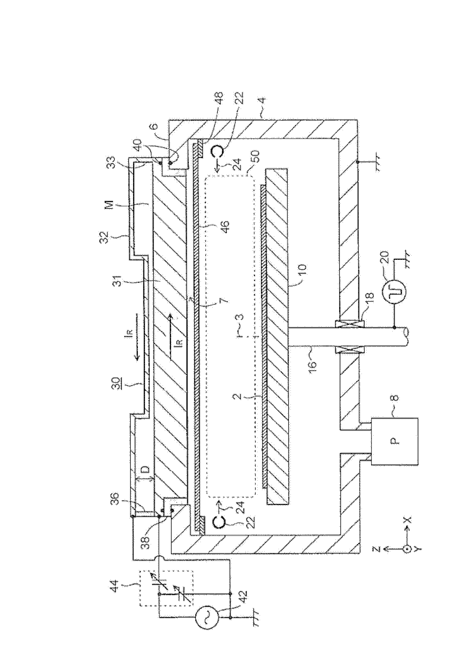
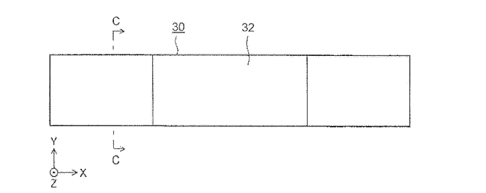
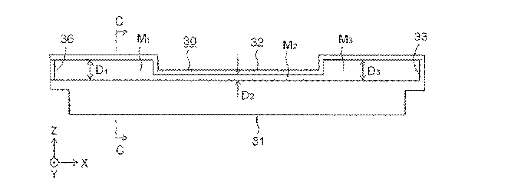
[0080] An embodiment of the plasma processing apparatus of the present invention is shown in figure 1 , And the antenna 30 is taken out and shown in Fig. 2(A), Fig. 2(B), and Fig. 2(C). In order to indicate the directions of the antenna 30 and the like, the X direction, the Y direction, and the Z direction that are orthogonal to one point are described in the figure. The Z direction is the direction in which the vertical line 3 standing on the surface of the substrate 2 is expanded and contracted, and the Y direction is the direction intersecting (for example, orthogonal to) the vertical line 3, and in order to simplify the expression as described above, the directions are respectively referred to as Up and down direction Z, left and right direction Y. The X direction is a direction crossing (for example, orthogonal) to the vertical line 3 and is the length direction of the antenna 30. For example, the X direction and the Y direction are horizontal directions, but they are not...


PUM


Abstract

The invention provides a plasma processing device which is an inductive coupling device and can reduce the effective inductance coefficient to restrain the plasma electrical potential more lower, and can control the plasma density distribution along the length direction through an antenna. Return conductors (31, 32) are arranged vertically on the vertical line (3) direction, namely the up and down direction (Z), of the surface of a substrate (2) and make the high frequency current (IR) flow retroactively to form an antenna with straight plane shape. The interval (D) of the up and down direction (Z) between the return conductors (31, 32) changes at the length direction (X).

Description

Technical field [0001] The present invention relates to a plasma processing device that uses plasma to perform, for example, plasma chemical vapor deposition (CVD, chemical vapour-phase deposition) on a substrate, etching, ashing, sputtering, and other processing, and more specifically In other words, it relates to an inductively coupled plasma processing apparatus that generates plasma by flowing a high-frequency current into an induced electric field generated by an antenna, and uses the plasma to process a substrate. Background technique [0002] As devices belonging to plasma processing devices that generate plasma at high frequencies, there are capacitively coupled plasma processing devices that generate capacitively coupled plasma (CCP), and inductively coupled plasma processing devices. plasma, referred to as ICP) inductively coupled plasma processing equipment. [0003] Simply put, a capacitively coupled plasma processing device applies a high-frequency voltage between two...

Claims


Application Information

Patent Timeline
Patent Type & Authority Applications(China)
IPC IPC(8): H05H1/46C23C16/505H01J37/32
CPCH01J37/321H01J37/3211C23C16/507H01L21/3065H05H1/46
Inventor 角田孝典松原克夫安东靖典辻藏行
Owner NISSIN ELECTRIC CO LTD
Why Eureka
Try Eureka