
Substrate Processing Apparatus for Mechanically Controlling Plasma Density

A substrate processing device and plasma technology, which are applied to circuits, discharge tubes, electrical components, etc., can solve the problems of inability to effectively control the plasma P density, inability to effectively control the plasma density, faster replacement cycle, etc., and achieve effective control. Effects of plasma density distribution, minimization of operation interruption time, and increased productivity

Active Publication Date: 2021-08-24
GIGALANE CO LTD
View PDF10 Cites 0 Cited by
  • Summary
  • Abstract
  • Description
  • Claims
  • Application Information

AI Technical Summary

Problems solved by technology

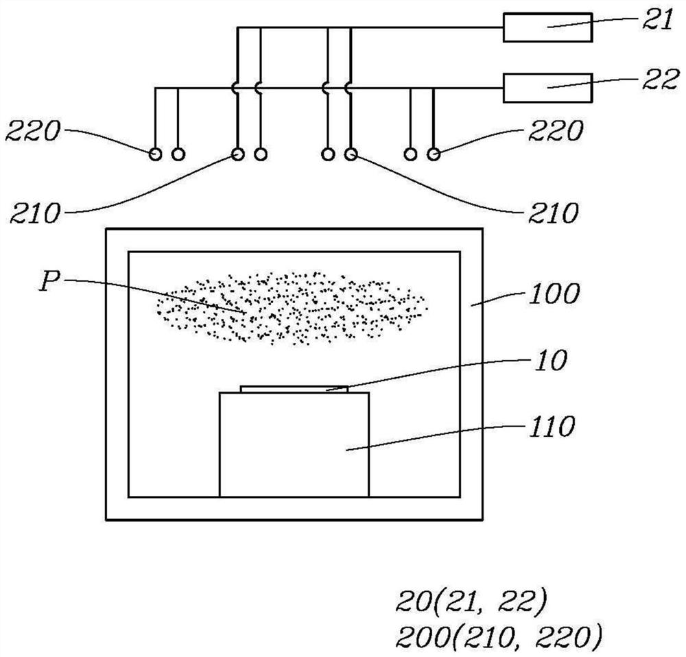
[0011] However, there is a problem that the high-frequency waves are affected by many environmental factors during the supply from the high-frequency power supply unit 20 to the antenna coil 200. Therefore, the high-frequency waves radiated from the antenna coil 200 cannot be effectively controlled as expected, and as a result, the plasma cannot be effectively controlled. P density
[0012] In addition, there is a problem that, in order to control high-frequency power, a plurality of electrical / electronic components are added, which increases management items, thereby making the replacement cycle faster
[0018] There is the same problem as the antenna coil 200 problem described above: the high-frequency waves radiated from the inner antenna coil 210 and the outer antenna coil 220 cannot be effectively controlled as expected, and as a result, the plasma density cannot be effectively controlled.
[0019] In addition, there is a problem that in order to separately control the high-frequency power supplied to the inner antenna coil 210 and the outer antenna coil 220, a plurality of electric / electronic configurations including the first high-frequency power supply unit 21 and the second high-frequency power supply unit 22 are added, Allows for a further increase in managed items, resulting in faster replacement cycles

Method used


Image

  • Substrate Processing Apparatus for Mechanically Controlling Plasma Density
  • Substrate Processing Apparatus for Mechanically Controlling Plasma Density
  • Substrate Processing Apparatus for Mechanically Controlling Plasma Density

Examples


Embodiment Construction

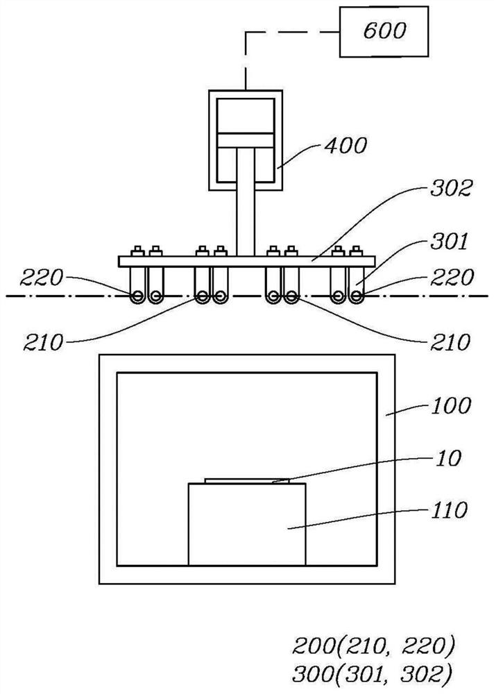
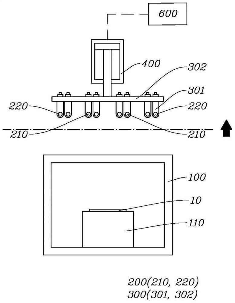
[0083] Such as Figure 2 to Figure 29 As shown, the substrate processing apparatus for mechanically controlling plasma density of the present invention includes a chamber 100 , a chuck 110 and an antenna coil 200 .

[0084] The substrate 10 is processed with plasma inside the chamber 100 .

[0085] At this time, the substrate 10 may be a wafer or a tray on which the wafer is mounted.

[0086] In addition, the substrate processing apparatus may be an apparatus that performs one or more of etching, vapor deposition, and ashing using plasma.

[0087] The substrate 10 is disposed on the chuck 110 and is disposed inside the cavity 100 .

[0088] The chuck 110 may be disposed at the upper or lower portion inside the cavity 100 according to the structure of the cavity 100 .

[0089] The antenna coil 200 is disposed outside the cavity 100 at a position corresponding to the chuck 110 via the substrate 10 .

[0090] The antenna coil 200 radiates high-frequency waves to the process g...


PUM


Abstract

The present invention relates to a substrate processing device for mechanically controlling the plasma density, which is characterized in that it includes a cavity for processing the substrate with plasma inside; an antenna coil for radiating high-frequency waves to the engineering gas supplied to the inside of the cavity to generating plasma; an interlocking part connected to the antenna coil and moving together with the antenna coil; a horizontal driving part providing driving force to move the interlocking part in a horizontal direction; and a drive control part controlling the horizontal driving of the drive unit, the drive control unit adjusts the driving amount of the horizontal drive unit in a manner corresponding to the moving direction and the moving distance from the current position of the antenna coil to the position to which the antenna coil should move, to This controls where the plasma is formed by the antenna coil.

Description

technical field [0001] The invention relates to a substrate processing device for controlling plasma density mechanically, in particular to a substrate processing device for controlling plasma density by adjusting the position of an antenna coil. Background technique [0002] The substrate processing apparatus is an apparatus for performing semiconductor processes, specifically, an apparatus for processing the substrate 10 with plasma P. [0003] At this time, the substrate 10 may be a wafer or a tray on which the wafer is mounted. [0004] In addition, the substrate processing apparatus may be an apparatus that uses plasma P to perform one or more of etching, vapor deposition, and ashing. [0005] In the substrate processing apparatus, the antenna coil radiates a high-frequency wave (High-frequency wave) to the process gas supplied into the chamber 100 to generate plasma P. [0006] At this time, the density of the generated plasma P affects the processing speed of the su...

Claims


Application Information

Patent Timeline
Patent Type & Authority Patents(China)
IPC IPC(8): H01J37/32
CPCH01J37/32623H01J37/3211
Inventor 郑相坤金亨源权赫俊郑熙锡
Owner GIGALANE CO LTD
Learn More