Stator punching piece lamination device

A stator punching and lifting device technology, applied in the field of lamination mechanism, can solve the problems of harmful workers' health and waist injury, and achieve the effect of ensuring physical health, reducing the number of times of bending, and improving safety

Active Publication Date: 2019-09-13
西安阿尔斯通永济电气设备有限公司
View PDF4 Cites 2 Cited by
  • Summary
  • Abstract
  • Description
  • Claims
  • Application Information

AI Technical Summary

Problems solved by technology

[0003] At present, the stacking of stator punching sheets is often done manually, including a cylindrical column placed on the ground in the vertical direction, and a plurality of stator punching sheets are stacked on one side of the column. During the process, it is often necessary for the staff to bend down to lift the stator punches placed next to them and then put them on a cylindrical column for lamination. Medium, easy to cause damage to the waist, harmful to the health of the staff

Method used


Image

  • Stator punching piece lamination device
  • Stator punching piece lamination device
  • Stator punching piece lamination device

Examples


Embodiment 1

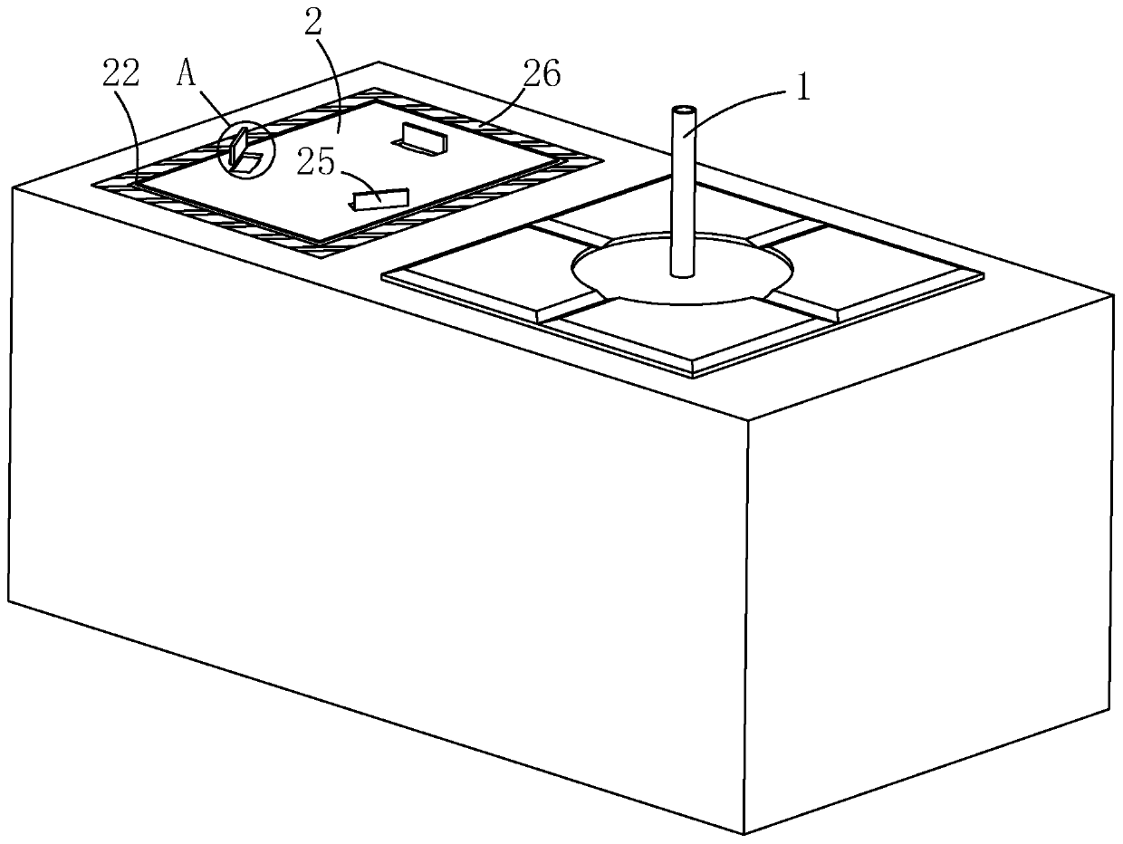
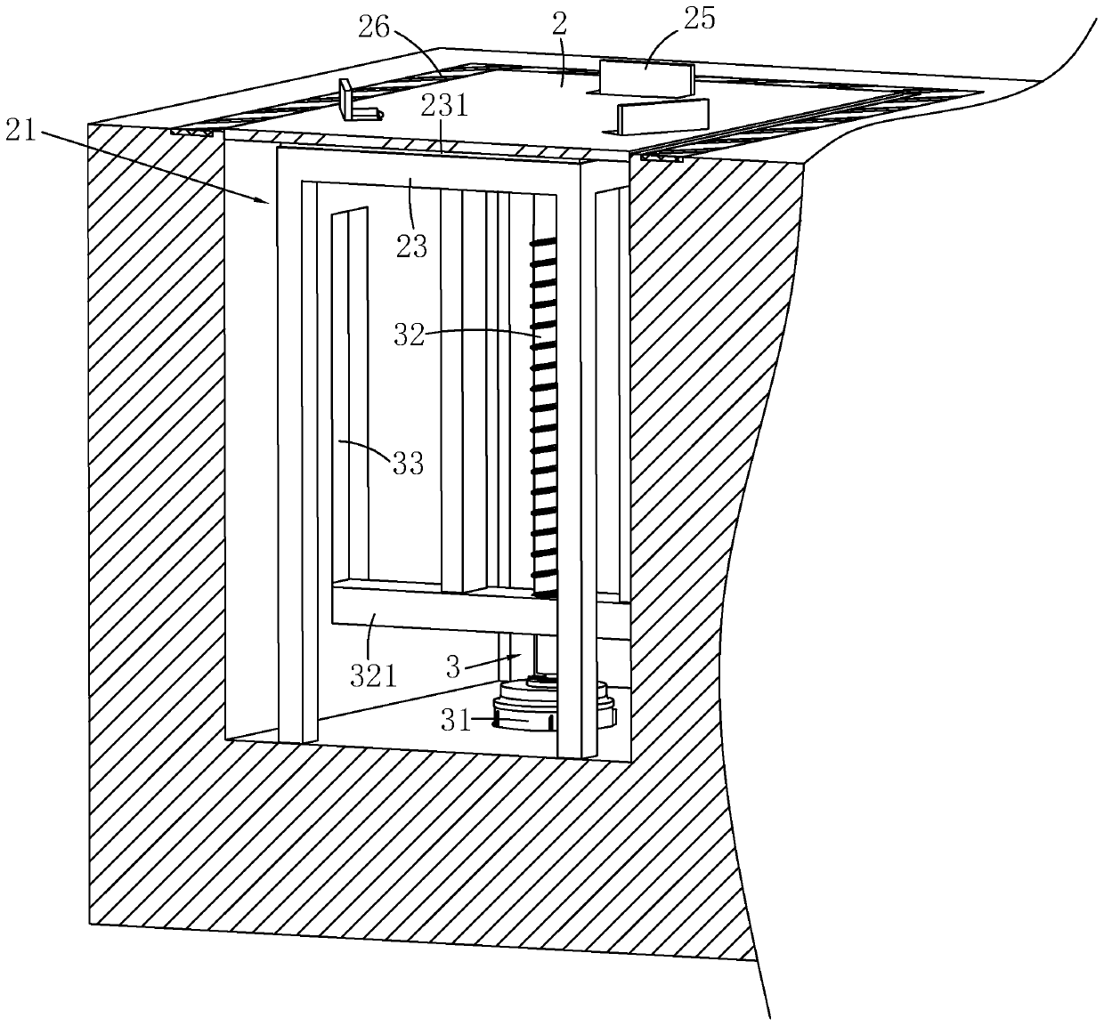
[0037] refer to figure 1 , is a stator punching lamination device disclosed in the present invention, which includes a cylindrical column 1 vertically arranged on the ground, and the side of the column 1 is provided with a placing platform 2 for placing stator punching pieces, and the ground There is a cavity 21 corresponding to the placement platform 2 on the upper side, wherein the side with the largest surface area of ​​the placement platform 2 is equal to the surface area of ​​the mouth of the cavity 21, and a warning line 26 is pasted around the cavity 21 on the ground around the mouth of the cavity 21 , warning line 26 is made of yellow and black reflective material.

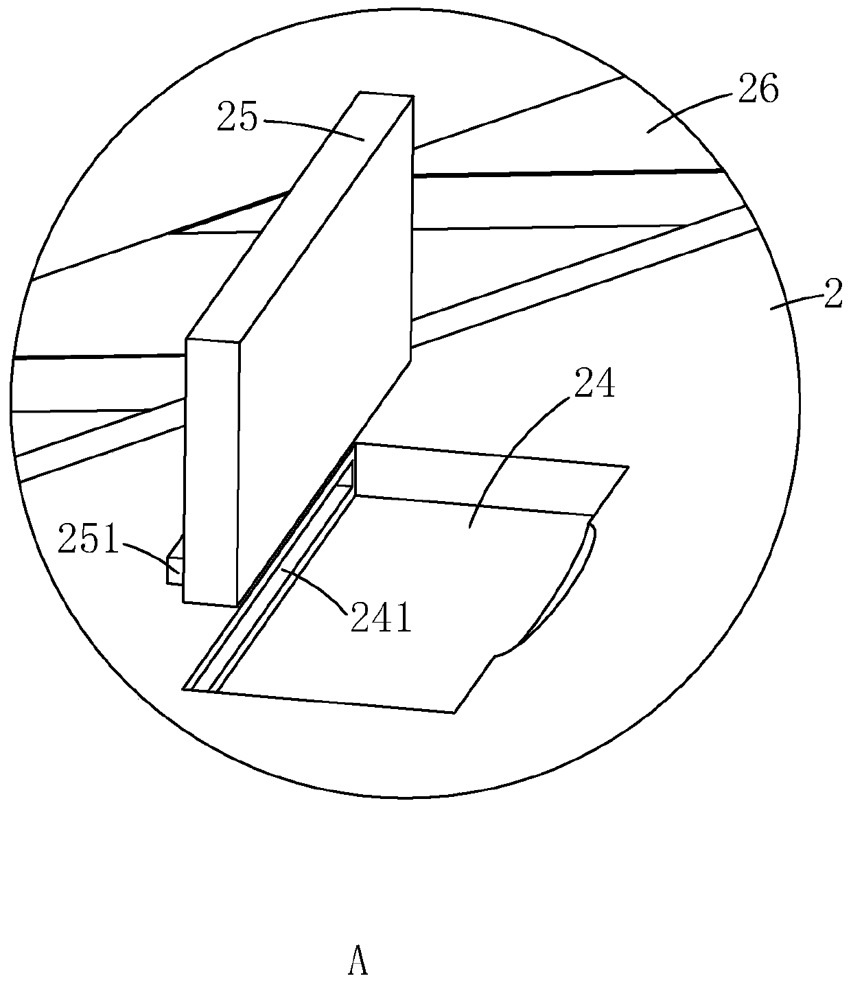
[0038] refer to figure 1 and figure 2 , the upper surface of the placement table 2 is provided with grooves 24, and there are at least three grooves 24. In this embodiment, there are three grooves 24, and the connecting line between two adjacent grooves 24 is An equilateral triangle is arranged; each g...

Embodiment 2

[0045] The difference between this embodiment and Embodiment 1 mainly lies in: Figure 4 As shown, the lifting device 3 includes a cylinder 34 vertically arranged on the bottom wall of the cavity 21 , and the piston rod of the cylinder 34 is fixedly connected to the bottom of the placing platform 2 . A right-angled triangle support plate 322 is provided between the piston rod of the cylinder 34 and the placement table 2, wherein one right-angled side of the support plate 322 is connected with the bottom of the placement platform 2, and the other right-angled side is connected with the piston rod of the cylinder 34.

[0046] The implementation principle of this embodiment is: when in use, turn over the limiting plate 25, turn the limiting plate 25 until the block 251 is engaged in the slot 241, at this time the limiting plate 25 will protrude from the groove 24 and remain vertical In this way, the stacked stator punches are placed between the limit plates 25, the limit plate 25...


PUM


Abstract

The invention relates to a stator punching piece lamination device. The stator punching piece lamination device comprises a cylindrical stand column which is arranged on the ground in the vertical direction; a placement table used for containing stator punching pieces is arranged on the side edge of the stand column, and a cavity is formed in the ground, corresponding to the placement table; a lifting device used for driving the placement table to rise and fall in the vertical direction is arranged between the placement table and the bottom wall of the cavity; the largest surface area on one plane of the placement table is equal to the surface area of the cavity; when the device is in use, the stator punching pieces are stacked on the placement table, a worker takes the stator punching pieces from the placement table, then the stator punching pieces positioned on the placement table are placed on the cylindrical stand column, and the lifting device is driven, so that the placement table can be lifted to the worker in the vertical direction, and the stator punching pieces positioned on the placement table can be taken down without needing the worker to bend down; and the device hasthe advantages that the bending frequency is reduced, the waist is not prone to being damaged, and the body health effect of the worker is guaranteed.

Description

technical field [0001] The technical field of lamination mechanism that the present invention relates to, in particular, relates to a lamination device for stator punching sheets. Background technique [0002] The motor stator is the key component of the motor. The motor stator must not only conduct magnetism but also place coils. When the motor is working, it must conduct magnetism and place coils. When the motor is working, it must bear the combined effects of mechanical vibration, electromagnetic force and heat. Today's motor stators generally use circular punching sheets. Stator punching stacking is to align (laminate), compress, and fix a certain number of stator punching sheets to form a compact and suitable whole with accurate dimensions and neat appearance. [0003] At present, the stacking of stator punching sheets is often done manually, including a cylindrical column placed on the ground in the vertical direction, and multiple stator punching sheets are stacked on...

Claims


Application Information

Patent Timeline
Patent Type & Authority Applications(China)
IPC IPC(8): H02K15/02H02K7/06
CPCH02K7/06H02K15/02
Inventor 宋海蛟田虎利李娟龚宝锋
Owner 西安阿尔斯通永济电气设备有限公司
Why Eureka
Try Eureka