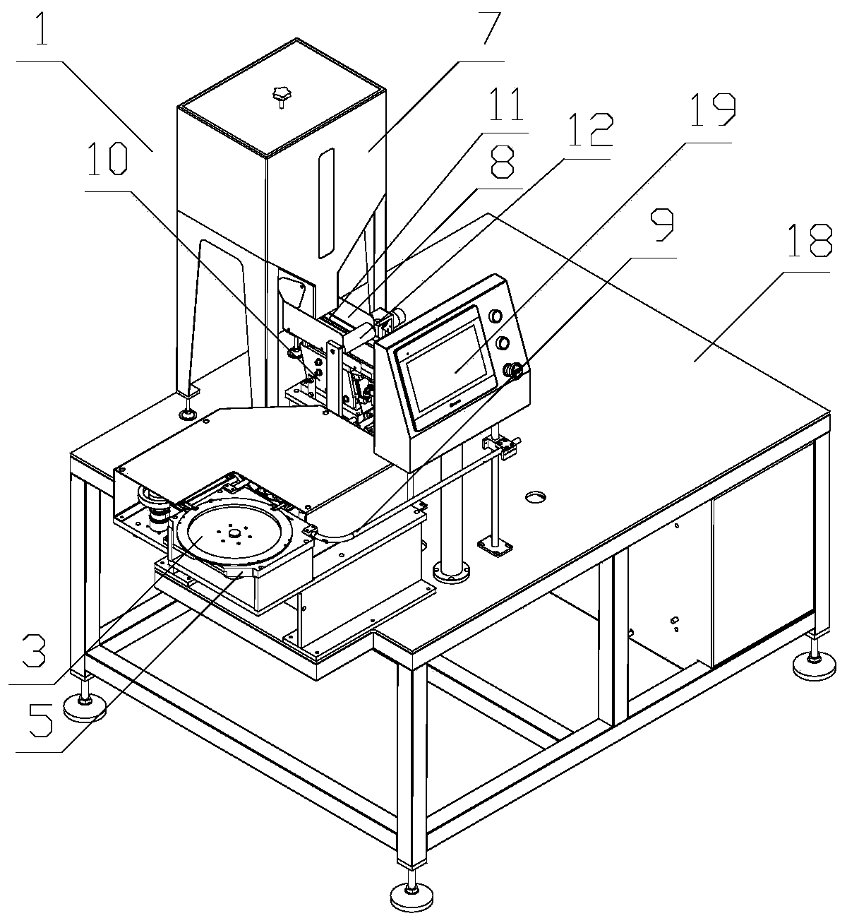
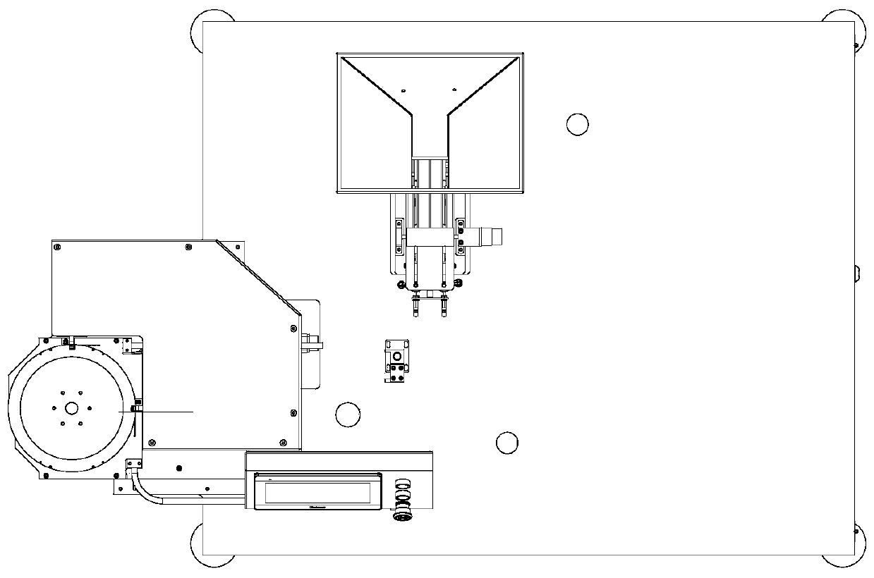
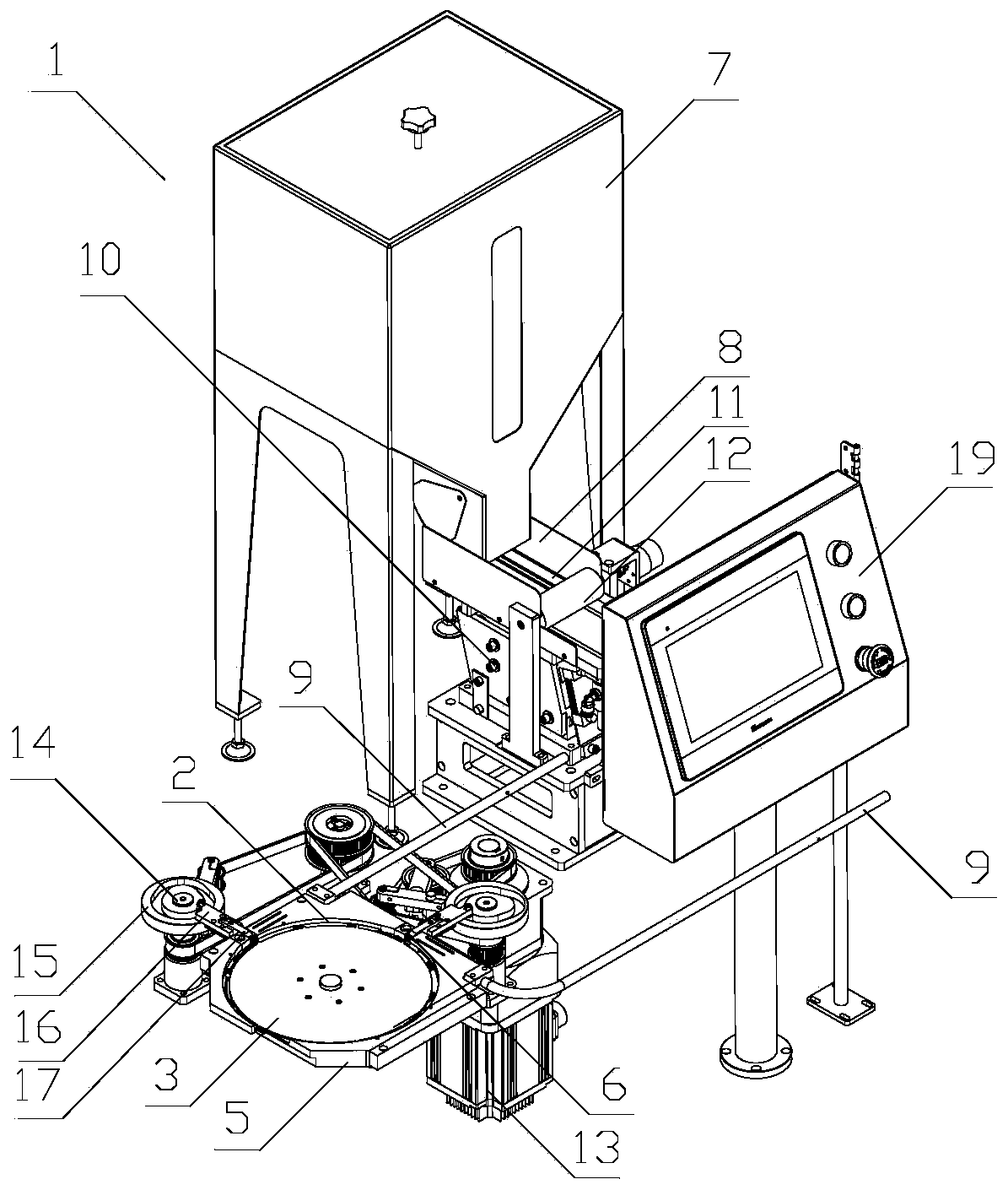
[0032] The principles and features of the present invention will be described below with reference to the accompanying drawings. The examples cited are only used to explain the present invention, and are not used to limit the scope of the present invention.
[0033] Such as Figure 1 to Figure 4 As shown, an online compounding device for cigarette water firmware includes a discharging assembly 1, a driving assembly, a horizontally arranged distributing runner 3, and an adsorption and conveying assembly 4. The distributing runner 3 is provided with an interval on the outer peripheral side wall A plurality of driving teeth, the outer periphery of the distributing runner 3 is provided with an inner hollow intermediate plate 5, and an arc-shaped groove for the passage of the water supply fixture is formed between the distributing runner 3 and the intermediate plate 2. The intermediate plate 5 is exposed on the outer peripheral side of the distributing runner 3, and the inner wall of the intermediate plate 5 is provided with a storage part 6 for accommodating the hydraulic components, and the adsorption and transmission assembly 4 is arranged on the The dividing wheel 3 extends below the edge on one side of the intermediate plate 5, and the suction and conveying assembly 4 is arranged on the dividing wheel 3 along the tangent direction of the index circle of the dividing wheel 3 Below, the discharge port of the blanking assembly 1 is in communication with the storage portion 6 and conveys the hydraulic components into the storage portion 6, and the drive assembly is used to transfer the The hydraulic fittings are sequentially dialed into the arc-shaped groove 2, and the drive assembly is also used to drive the distributing wheel 3 to rotate, so that the drive teeth drive into the arc-shaped groove 2 The water fixture moves above the adsorption and transfer assembly 4, and the adsorption transfer assembly 4 absorbs the water fixture that moves above it, and transports it to the bottom of the cigarette holder composite device, and the cigarette holder composite device inserts the cigarette stick into the phase Between the two adjacent fasteners, the adsorption and transfer assembly 4 transports the fasteners and fabric to the winder and rolls them into shape.
[0034] In the on-line composite device for cigarette water fixture of the present invention, the water fixture shrinkage fixture is transported to the storage part of the inner wall of the intermediate plate through the blanking assembly, the driving assembly drives the distributing runner to rotate, and the driving assembly rotates the The hydraulic components in the storage part are pushed into the arc-shaped grooves, so that the hydraulic components in the grooves rotate to the upper part of the adsorption and conveying assembly with the feed roller under the action of the driving teeth. The adsorption component adsorbs the water fixture above it so that the water fixture falls onto it, and is transported to the bottom of the cigarette holder composite device to complete the on-line composite of the water fixture, which realizes the online precision composite of the water fixture and greatly improves the composite efficiency of the water fixture. , And to ensure that the direction of the water-firmware composite is correct, to ensure the consumer experience.
[0035] In one or more embodiments provided by the present invention, the blanking assembly 1 includes a blanking bin 7, a sorting bin 8 and a pneumatic conveying pipe 9, and the blanking bin 7 is located above the sorting bin 8. And the discharge end of the lower bin 7 extends into the sorting bin 8, the sorting bin 8 is arranged obliquely, and the sorting bin 8 is close to the height of one end of the discharge opening of the lower bin 7 Higher than the other end, the other end of the sorting bin 8 is in communication with one end of the pneumatic conveying pipe 9, and the other end of the pneumatic conveying pipe 9 extends into the intermediate plate and is connected to the storage part 6. Connected. The water components falling from the discharge port of the lower silo 7 are preliminarily sorted through the sorting silo 8, and transferred to the pneumatic conveying pipe 9, which is conveyed to the storage by the pneumatic conveying pipe 9 In the feeding section 6, automatic feeding is realized, which greatly improves the production efficiency.
[0036] In one or more embodiments provided by the present invention, the upper end of the lower silo 7 is opened, and the upper end of the lower silo 7 is provided with a cover for opening or closing the opening. 7 An observation window is provided on the side wall near the other end of the sorting bin 8, and a transparent glass sheet is embedded in the observation window. By providing an opening at the upper end of the lower silo 7, it is easier to replenish the lower silo 7, and the cover plate can isolate the inner space of the lower silo 7 from the external environment to ensure The interior is clean and sanitary. By setting an observation window and setting glass sheets at the observation window, it is convenient for the staff to observe the amount of remaining material in the lower silo 7 at any time.
[0037] Preferably, the lower silo 7 is also provided with a sensor for detecting whether the amount of material in the lower silo 7 is lower than a preset material amount threshold. A capacitance sensor can be used, and the capacitance sensor and the lower silo 7 can be used. The electrical capacity between the side walls of the silo is used to determine whether the amount of material in the lower silo 7 is lower than the preset material amount threshold. How to determine it as the prior art will not be repeated in the present invention.
[0038] In one or more embodiments provided by the present invention, the bottom of the sorting bin 8 is provided with a vibrating mechanism 10, and the inner bottom wall surface of the sorting bin 8 is provided with a strip through which the water supply fastener passes along its length direction. The middle surface of the bin 8 is provided with a sorting wheel 12 along its width direction. The strip-shaped slot 11 is connected to one end of the pneumatic conveying pipe 9 at one end away from the lower bin 7. By setting the vibrating mechanism 10, the hydraulics in the sorting bin 8 can move to the lower end of the sorting bin 8, and the sorting wheel 12 and the strip groove 11 can cooperate to control the sorting bin. The water fixtures in the silo 8 are arranged, and the water fixtures are transported to the pneumatic conveying pipe 9 in a uniform posture through the strip groove 11 to realize the arrangement of the water fixtures.
[0039] In the present invention, the vibrating mechanism 10 is in a direct vibrator, and the specific structure is the prior art, which will not be described in detail in the present invention, and this is not within the scope of protection required by the present invention.
[0040] In one or more embodiments provided by the present invention, the drive assembly includes a drive motor 13 and a toggle mechanism. The drive motor 13 is in transmission connection with the material distributing wheel 3 and drives the material distributing wheel 13 Rotating, the toggle mechanism is arranged on the outer periphery of the intermediate plate 5 and is located at the corresponding position of the storage portion 6, the drive motor 13 is in transmission connection with the toggle mechanism, and the drive motor 13 drives the The dialing mechanism periodically extends into the storage portion 6 and dials the hydraulic components into the arc-shaped groove 2, and the driving motor 13 drives the driving teeth on the distributing wheel 13 to drive The hydraulic components entering the arc-shaped groove 2 move to the top of the adsorption and transmission assembly 4. The driving motor can respectively drive the driving wheel 3 and the toggle mechanism to move, and the toggle mechanism periodically extends into the storage portion 6, so that the toggle mechanism can be accurate The hydraulic components in the storage portion 6 are accurately pushed into the arc-shaped groove 2 so as to defend that the subsequent hydraulic components are accurately adsorbed on the adsorption and transmission assembly, so as to realize the precise combination of the hydraulic components.
[0041] In one or more embodiments provided by the present invention, the toggle mechanism includes a rotating shaft 14, a cam mechanism 15, a toggle body 16, and a toggle lever 17, and the cam 15 mechanism is arranged at the upper end of the rotating shaft 14. The toggle body 16 is disposed between the cam mechanism 15 and the corresponding storage portion 6 on the intermediate plate 5, and the toggle lever 17 penetrates through the toggle body and its two ends extend respectively. Outside the toggle body 16, one end of the toggle lever 17 is provided with a roller, and the roller is locked into the cam groove of the cam mechanism 15, and the other end of the toggle lever 17 faces the storage. The material part 6 is provided, and the drive motor 13 is in transmission connection with the rotating shaft 14, and drives the rotating shaft 14 to drive the cam mechanism 15 to rotate, and the cam mechanism 15 rotates and drives the other end of the toggle lever 17 Periodically extend into the storage portion 6 and push the hydraulic fasteners located in the storage portion 6 into the arc-shaped groove 2. The rotating shaft 14 is driven by the drive motor 13 to drive the cam mechanism 15 to rotate, so that the cam mechanism 15 can periodically extend into or out of the storage portion 6, thereby realizing the transfer of the split material The hydraulic components in the wheel 3 are accurately dialed into the arc-shaped groove 2. Here, the cam mechanism 15 is a groove cam.
[0042] In one or more embodiments provided by the present invention, the number of the storage part 6, the pneumatic conveying pipe 9, the strip groove 11 and the toggle mechanism are all two, and the two storage parts 6 surround the The outer circumference of the distributing runner 3 is arranged at an included angle, and the end of the strip groove 11 away from the lower silo 7 is connected to the corresponding end of the pneumatic conveying pipe 9. The other end extends into the middle plate and communicates with the corresponding storage part 6, the toggle mechanism is arranged on the outer periphery of the middle plate 5 and is located at the corresponding position of the storage part 6, so The driving motor 13 is respectively drivingly connected with the two toggle mechanisms, and the toggle mechanism pushes the hydraulic components located in the corresponding storage portion 6 into the arc-shaped groove 2. By setting the number of the storage part 6, the pneumatic conveying pipe 9, the strip groove 11 and the toggle mechanism to two, the hydraulic components in the storage part 6 can be dialed into the corresponding place at the same time. In the groove, it can be rolled into two cigarettes at a time when the subsequent wrapping paper is rolled, and then cut into two cigarettes from the middle position, so that the production efficiency of the device can be doubled.
[0043] In one or more embodiments provided by the present invention, the cigarette water-firmware online compounding device further includes a workbench 18, and the blanking assembly 1 and the distributing wheel are respectively arranged on the workbench 1. The driving motor 13 is arranged under the working table 18, and the output end of the driving motor 13 passes upward through the working table 18 and is respectively connected to the distributing wheel 3 and the toggle mechanism in transmission. The worktable 1 can separately support the unloading assembly 1 and the distributing wheel stably, and can be used as a support for the drive motor 13, to ensure the stable operation of the entire device, and at the same time to integrate the entire device. Easy to transfer and transport.
[0044] In one or more embodiments provided by the present invention, the online combination device for cigarette water firmware further includes an interactive panel 19, which is arranged on the workbench 18, and the interactive panel 19 is connected to the The blanking assembly 1 and the driving motor 13 are electrically connected. Through the interactive panel 19, the blanking assembly 1 and the driving motor 13 can be adjusted, set and controlled respectively, so as to ensure the stable cooperation of various parts, so that the entire device runs smoothly and stably. The interactive panel 19 is provided with buttons and a display. The buttons include a start button, a stop button, etc. The display is a touch screen, which is used to set the working parameters of each component and display the working status and working parameters of each component. In the foregoing embodiment, when the sensor detects that the amount of material in the lower silo 7 is lower than the preset material amount threshold, the display will display an alarm message to remind the staff to clothe in time.
[0045] Such as Figure 5 As shown, in one or more embodiments provided by the present invention, the suction conveyor assembly 4 is an endlessly moving suction belt, and the suction belt is along the tangent direction of the index circle of the dividing wheel 3. It is arranged below the material dividing wheel 3 and is arranged in contact with the edge of the lower surface of the material dividing wheel 3 protruding from the intermediate plate 5. The surface of the suction belt is evenly spaced with a plurality of The suction hole, the suction belt is arranged below the edge of the distributing wheel 3 on one side of the intermediate plate 5, and the internal negative pressure of the suction belt moves to it through the suction hole. The upper moisture element is adsorbed so that the moisture element falls onto the suction belt, and the moisture element is transported to the bottom of the cigarette holder composite device. Through the negative pressure in the suction belt and the suction hole, the water element moving above it can be adsorbed, so that the water element falls on the suction belt and is in accordance with the distributing runner 3 The interval is fixed on the suction belt, so that the cigarette rod can be accurately released between the two adjacent water components, and the online composite of the water components can be accurately completed. Here, the suction belt is arranged on the index circle of the dividing wheel 3 directly below the tangential direction perpendicular to the direction in which the intermediate plate 5 extends.
[0046] In the present invention, the above-mentioned cigarette holder composite device processes the hydraulic fasteners and cigarette sticks on the suction belt to wrap paper rolls, form cigarettes, and cut cigarettes, and the corresponding equipment is the prior art, which will not be described in detail in the present invention.
[0047] The above descriptions are only preferred embodiments of the present invention and are not intended to limit the present invention. Any modification, equivalent replacement, improvement, etc. made within the spirit and principle of the present invention shall be included in the protection of the present invention. Within range.