Endovascular Surgical Instruments

A technology for surgical instruments and handles, applied in the field of medical instruments, can solve the problems of size limitation, increase of patient scars, and impact on appearance.

Active Publication Date: 2020-11-27
毛张凡
View PDF10 Cites 0 Cited by
  • Summary
  • Abstract
  • Description
  • Claims
  • Application Information

AI Technical Summary

Problems solved by technology

The long-rod surgical forceps occupy the operating space and affect the operation of the surgeon. At the same time, the increased incision will increase the trauma and pain of the patient, and will also increase the scars on the patient's body surface, affecting the appearance
In addition, the current laparoscopic surgical instruments are mostly integrated and cannot be disassembled, so the size of the operating part in the cavity is often limited by the size of the connecting rod

Method used


Image

  • Endovascular Surgical Instruments
  • Endovascular Surgical Instruments
  • Endovascular Surgical Instruments

Examples


Embodiment 1

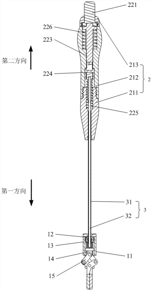
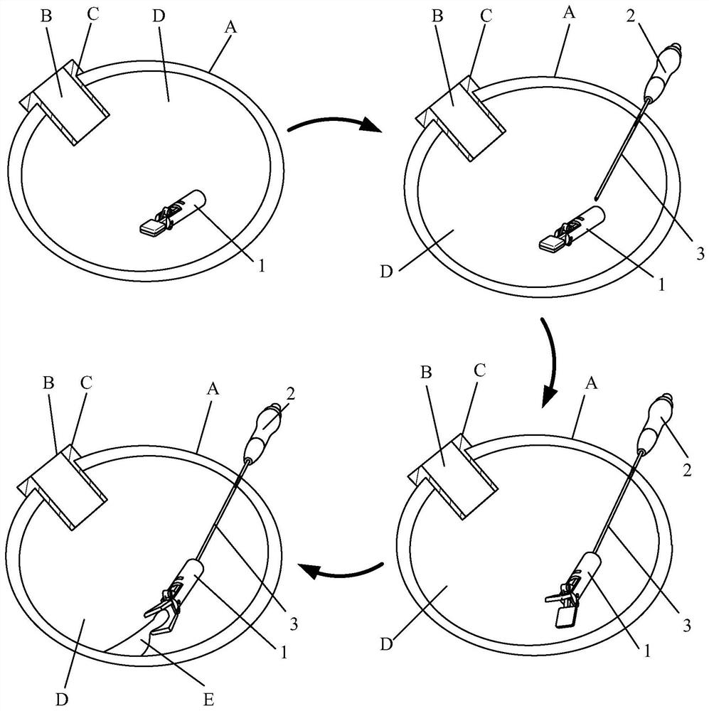
[0093] figure 1 is a schematic diagram of an intracavity surgical instrument according to an embodiment of the present invention. The intracavitary surgical instrument includes an operating device 1 and a handle 2, the handle 2 is provided with a connecting rod 3, and the connecting rod 3 includes a hollow sleeve rod 31 and a core rod 32 movably arranged in the sleeve rod 31, The connecting rod 3 has a pointed end. figure 2 It is a schematic diagram of the operation of the intracavity surgical instrument according to the first embodiment of the present invention. Such as figure 2 As shown, when performing intracavitary surgery, the doctor opens a puncture hole B on the patient's body surface A according to needs, and then inserts a puncture cannula C corresponding to the size of the puncture hole B into the puncture hole B to form a passage for surgical instruments to enter and exit , and then the operating device 1 is placed in the cavity D through the puncture cannula ...

Embodiment 2

[0111] Such as figure 2 As shown, the intracavitary surgical device includes an operating device 1 and a handle 2, the handle is provided with a connecting rod 3, and the connecting rod 3 includes a hollow sleeve rod 31 and a core rod movably arranged in the sleeve rod 31 32. The connecting rod 3 has a pointed end. Such as figure 2 As shown, when performing intracavitary surgery, the doctor opens an incision B on the patient's body surface A according to needs, and then inserts a puncture cannula C (trocar) corresponding to the size of the incision B into the incision B to form a channel for surgical instruments to enter and exit , and then place the operating device 1 in the cavity D through the puncture cannula C; the user holds the handle, and inserts the tip of the connecting rod 3 into the cavity D through other positions on the patient's body surface A; The operation is performed in the cavity D, and the connecting rod 3 is fixedly connected with the operating device...

Embodiment 3

[0116] Figure 21 It is a schematic diagram of the opened state of the operating device of the intracavitary surgical device in this embodiment, Figure 22 It is a schematic diagram of the closing state of the operating device of the intracavitary surgical device of this embodiment. Such as Figure 21 and Figure 22 As shown, the structure of the intracavitary surgical device of this embodiment is basically the same as that of the first or second embodiment, the only difference is:

[0117] Such as Figure 21As shown, in the natural state (no external force), the push rod 14 is in the initial position, the angle between the two connecting arms 152b is small, and the distance between the two connecting points of the curved rod 152a and the connecting arm 152b is the shortest. The pliers head 15 is in an open state. When the core rod 32 is controlled to move in the first direction, the first end of the core rod 32 pushes the push rod 14 to move in the first direction, so th...


PUM


Abstract

Disclosed is an endoluminal surgery instrument, comprising an operating device (1) and a handle (2). The operating device (1) comprises an operating portion (11) and a connecting portion (12). The handle (2) is provided with a connecting rod (3), the connecting rod (3) has a tip portion, and the tip portion of the connecting rod (3) is connected to the operating device (1). The connecting rod (3) comprises a hollow sleeve rod (31) and a core rod (32) movably arranged in the sleeve rod (31), and the core rod (32) can be controlled to stay in different positions by means of operating the handle (2) so as to enable the operating device (1) to open or close. During an operation, the operating device (1) is placed in a lumen (D) via an incision (B), the tip portion of the connecting rod (3) enters the lumen (D) along a puncture point and is fixedly connected to the connecting portion (12) of the operating device (1), and the handle (2) is then operated in vitro such that the operating portion (11) can be controlled to implement a corresponding surgical operation. The diameter of the tip portion of the connecting rod (3) is less than 3 mm, such that the puncture point does not need to be stitched up, thereby reducing injury to the body of a patient. Moreover, since the operating device (1) can be detached from the handle (2), the size of the operating device (1) is not limited by the diameter of the connecting rod (3), such that it is possible to perform the surgical operation in vitro more conveniently.

Description

technical field [0001] The invention relates to the field of medical instruments, in particular to an intracavitary surgical instrument. Background technique [0002] In minimally invasive surgery, since the surgeon's hand cannot enter the patient's body cavity, the body tissue that needs to be operated on is often covered by its own hanging tissue, partially cut free tissue, or internal organs (such as liver, spleen, lung), etc. Therefore, These tissues or organs must be turned to fully expose the surgical operation site and continue the surgical process. [0003] At present, in laparoscopic surgery, 3-4 incisions B of 5-12 mm are generally made on the body surface A through a puncture cannula C, such as Figure 25 shown. Then the long rod surgical instrument F is stretched into the cavity D through the passage of the puncture sleeve C to perform the operation, such as Figure 26 shown. When it is necessary to pull the tissue or organ E in the cavity to expose the operat...

Claims


Application Information

Patent Timeline
Patent Type & Authority Patents(China)
IPC IPC(8): A61B17/02
CPCA61B17/0218
Inventor 毛张凡毛航
Owner 毛张凡
Why Eureka
Try Eureka