Synchronous valve device of breathing machine

A valve device and ventilator technology, applied in respirator and other directions, can solve the problems of increasing infarction, complexity, and inability to optimize CO2 removal, and achieve the effect of high valve opening sensitivity and accurate breathing rhythm synchronization.

Inactive Publication Date: 2019-09-17
JILIN UNIV FIRST HOSPITAL
View PDF5 Cites 0 Cited by
  • Summary
  • Abstract
  • Description
  • Claims
  • Application Information

AI Technical Summary

Problems solved by technology

However, the actual tubes of traditional mechanical ventilators (such as endotracheal tubes) and other devices used to manage respiratory assistance to the patient use a lumen design and contribute to no-lumen ventilation
For this reason CO2 removal cannot be optimized
[0003] Previous attempts to improve CO2 removal from endotracheal tubes included multi-lumen designs designed to introduce gas flow through side lumens to remove CO2 f...

Method used


Image

  • Synchronous valve device of breathing machine

Examples


Embodiment Construction

[0010] The principles and features of the present invention are described below in conjunction with the accompanying drawings, and the examples given are only used to explain the present invention, and are not intended to limit the scope of the present invention.

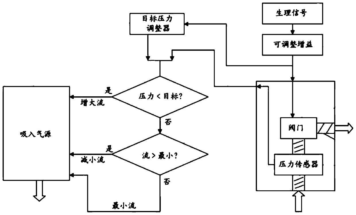
[0011] Such as figure 1 As shown, a synchronous valve device of a ventilator has a device housing, a valve cover, an air inlet and an air outlet, and also includes a conduit connected to the air outlet, which is used to connect to the patient's airway; the suction conduit lumen is connected to to the conduit; an expiratory conduit lumen connected to the conduit; an inspiratory gas source connected to the inspiratory conduit lumen through an air inlet; and a pressure control to control the pressure in the expiratory conduit lumen The pressure controller is responsive to a physiological breathing signal representative of the patient's inspiratory effort, allowing unrestricted airflow through the expiratory catheter lu...


PUM


Abstract

The invention relates to a synchronous valve device of a breathing machine. The device comprises a device shell, a valve cover, an air inlet and an air outlet. The device further comprises a conduit which is connected to the air outlet and used for being connected to the respiratory tract of the patient; an inhalation conduit lumen which is connected to the conduit; an exhalation conduit lumen which is connected to the conduit; an inhalation air source which is connected to the inhalation conduit lumen through the air inlet; and a pressure controller which controls the pressure in the exhalation conduit lumen. The pressure controller is corresponding to the physiological respiratory signal of the patient, and can balance the static cover pressure of the valve cover with the inhalation pressure: the front shell cavity and the rear shell cavity are hermetically connected, and are communicated with each other through the port of the valve cover, and the air outlet at the front end is externally connected to an air delivery pipe. Because the closing pressure of the valve cover is balanced with the inhalation pressure, the valve opening sensitivity is high, and the device can meet the accurate synchronization requirement of the respiratory rhythm of the patient under the weak respiratory state.

Description

technical field [0001] The invention relates to the field of ventilator devices, in particular to a synchronous valve device for a ventilator. Background technique [0002] In current ventilator devices, efforts have been made to minimize the dead space or dead volume introduced in the breathing circuit of a mechanical ventilator. However, the actual tubes of traditional mechanical ventilators (eg endotracheal tubes) and other devices used to manage respiratory assistance to a patient use a lumen design and contribute to no-lumen ventilation. For this reason, CO2 removal cannot be optimized. [0003] Previous attempts to improve CO2 removal from endotracheal tubes included multi-lumen designs designed to introduce gas flow through side lumens to remove CO2 from the main lumen, but this approach did not completely eliminate patient re-breath during inspiration volume. Therefore, the proposed method reduces, but does not optimize CO2 removal and minimize CO2 rebreathing pro...

Claims


Application Information

Patent Timeline
IPC IPC(8): A61M16/20
CPCA61M16/20A61M16/204
Inventor 华树成
Owner JILIN UNIV FIRST HOSPITAL
Why Eureka
Try Eureka