Oil pump vehicle evacuation oil-gas separator

A separation device and vacuum pumping technology, which is applied in the direction of separation methods, liquid degassing, chemical instruments and methods, etc., can solve the problems of high investment cost, excessive gas, and small diameter of vacuum pumping pipelines, so as to improve the opening sensitivity and reduce the The effect of using cost and reducing labor input

Inactive Publication Date: 2013-10-23
LOGISTICAL ENGINEERING UNIVERSITY OF PLA
View PDF7 Cites 3 Cited by
  • Summary
  • Abstract
  • Description
  • Claims
  • Application Information

AI Technical Summary

Problems solved by technology

The evacuation pipeline connected to the outlet of the auxiliary oil pump and the main oil pump is small in diameter and short in length. During the vacuuming process, the oil flow in this pipeline is fast. If there is too much gas, it cannot be put into normal work. On the contrary, if the vacuum pipeline cannot be cut off in time, the oil will enter the exhaust system through the auxiliary oil pump, which will inevitably bring a lot of corresponding oil collection and oil recovery work.
When the above-mentioned oil-gas separator is working, when the oil-gas interface rises and the float floats to close the main valve, there may be a situation where a large amount of oil-gas mixture enters the oil-gas separator, making the oil-gas interface in the oil-gas separator very blurred. The direct-acting sensor may have incorrectly cut off the pumping path, or frequently fluctuates up and down to cause unstable pumping; the auxiliary personnel directly open and close the manual deflation valve based on actual experience, and cannot complete the vacuuming operation effectively, accurately and in a timely manner, resulting in the above problems , so that a large number of corresponding oil collectors and oil recovery workers have high input costs and high use costs
[0007] In summary, the oil-gas separators in the prior art are not exhausted completely, have low oil-gas separation efficiency and high cost of use

Method used


Image

  • Oil pump vehicle evacuation oil-gas separator
  • Oil pump vehicle evacuation oil-gas separator

Examples


Embodiment Construction

[0018] The present invention will be further described below in conjunction with the drawings and embodiments:

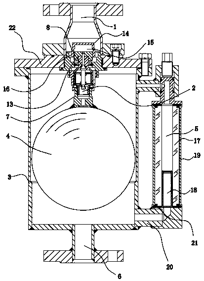
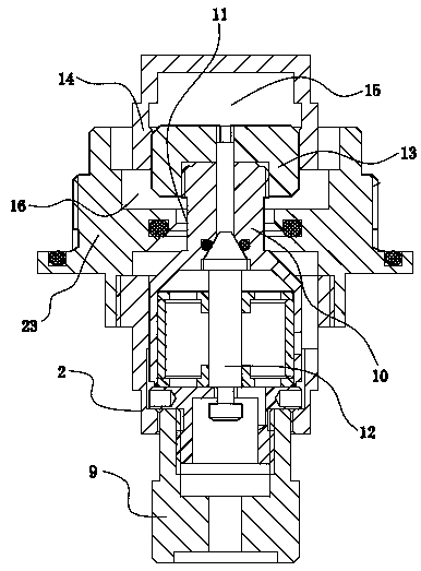
[0019] See attached figure 1 with 2 , An oil pump truck vacuum oil and gas separation device, comprising a casing 3, arranged at the bottom of the casing 3 for connecting with the main oil pump on the vacuum pipeline, the oil and gas inlet channel 6 arranged on the top of the casing 3 for connecting with the vacuum pipe The exhaust passage 1 connected by the auxiliary oil pump on the road, the oil and gas inlet passage 6 and the exhaust passage 1 are both in communication with the inner cavity of the housing 3, and a floating ball 4 is arranged in the inner cavity of the housing 3; : An exhaust valve 2 is fixed on the top of the float 4, and the exhaust valve 2 includes a main valve 7 and a pilot valve 8;

[0020] The bottom of the valve body 9 of the main valve 7 is fixed on the top of the float 4, the valve core 10 on the top of the valve body 9 matches the valve port ...


PUM


Abstract

The invention relates to a vehicle-mounted oil-gas separator, and especially relates to an oil pump vehicle evacuation oil-gas separator. The oil-gas separator comprises a shell, an oil gas entrance channel arranged at the bottom of the shell, and an exhaust channel arranged at the top of the shell, the oil gas entrance channel and the exhaust channel are respectively communicated with the inner cavity of the shell, and a floating ball is arranged in the inner cavity of the shell; an exhaust valve is fixed at the top of the floating ball, and comprises a main valve and a guiding valve; the valve core of the main valve is coupled with the valve port at the top of the shell to make the floating ball float up and down to drive the valve core to open or close the valve port in order to realize the communication or closure between the exhaust channel and the inner cavity of the shell; and the balance valve core of the guiding valve is fixed in the inner cavity of the body of the guiding valve, the piston of the guiding valve is fixed at the top of the valve core, and a separation board is sleeved outside the piston to form a reverse thrust cavity between the piston and the separation board. The oil pump vehicle evacuation oil-gas separator having the above structure has the advantages of thorough exhaust, increase of the oil-gas separation efficiency, and reduction of the use cost.

Description

Technical field [0001] The invention relates to a vehicle-mounted oil and gas separation device, in particular to a vacuum oil and gas separation device for an oil pump truck that exhausts thoroughly, improves the efficiency of oil and gas separation and reduces the use cost. Background technique [0002] A typical filter separator in the prior art is mainly composed of a housing, a separation filter element, a coalescing filter element, a double needle pressure gauge, an automatic air release valve, a manual air release valve, an automatic water release valve, and a manual water release valve. [0003] The separation filter element is the second-stage oil-water separation element in the separator, which is made of stainless steel wire mesh with a mesh of 100 mesh / in and sprayed with highly water-repellent polytetrafluoroethylene. It is fixed on the cross joint at the lower end of the outlet by a central screw. [0004] The coalescing filter element is the first stage oil-water ...

Claims


Application Information

Patent Timeline
Patent Type & Authority Applications(China)
IPC IPC(8): B01D19/00
Inventor 左永刚陈军张雪梅杨静张镇于江叶有义王涛
Owner LOGISTICAL ENGINEERING UNIVERSITY OF PLA
Why Eureka
Try Eureka