Eureka AIR delivers breakthrough ideas for toughest innovation challenges, trusted by R&D personnel around the world.

Pre-machining combined wire drawing machine for metal product

A metal product and pre-processing technology, applied in the direction of wire drawing dies, etc., can solve the problems of reducing the quality of steel wire drawing, dislocation of internal lattice structure, easy wire breakage, etc., and achieve the goals of avoiding a sharp drop in temperature, good mechanical properties, and good thermal insulation properties Effect

Active Publication Date: 2019-09-17
泰州市鑫中汇金属材料科技有限公司
View PDF8 Cites 3 Cited by
  • Summary
  • Abstract
  • Description
  • Claims
  • Application Information

AI Technical Summary

Problems solved by technology

[0003] The wire drawing structure of the existing coupled wire drawing machine is divided into two types: fixed die and roller die. The structure of the fixed die is as follows: figure 1 As shown, by passing the steel wire through one end of the tapered hole opened on the stent, and pulling the steel wire out from the small end, the effects of reducing the cross-sectional area of ​​the steel wire and smoothing the surface can be achieved. Because the structure relies on the hard extrusion between the steel wire and the fixed die, a large amount of heat will be generated due to sliding friction between the steel wire and the inlet of the tapered hole, resulting in adhesion between the steel wire and the fixed die. In order to ensure the next pass The smooth drawing of the steel wire must wait for the steel wire to be fully cooled, that is, to slow down the speed of the wire, which will further aggravate the adhesion between the steel wire and the fixed die, and reduce the quality of the steel wire drawing. Rapid cooling causes strong work hardening on the surface of the steel wire, dislocation of the internal lattice structure, a large difference between the surface hardness of the steel wire and the central hardness, and the wire is easy to break

Method used


Image

  • Pre-machining combined wire drawing machine for metal product
  • Pre-machining combined wire drawing machine for metal product
  • Pre-machining combined wire drawing machine for metal product

Examples


Embodiment Construction

[0024] The following will clearly and completely describe the technical solutions in the embodiments of the present invention with reference to the accompanying drawings in the embodiments of the present invention. Obviously, the described embodiments are only some, not all, embodiments of the present invention. Based on the embodiments of the present invention, all other embodiments obtained by persons of ordinary skill in the art without making creative efforts belong to the protection scope of the present invention.

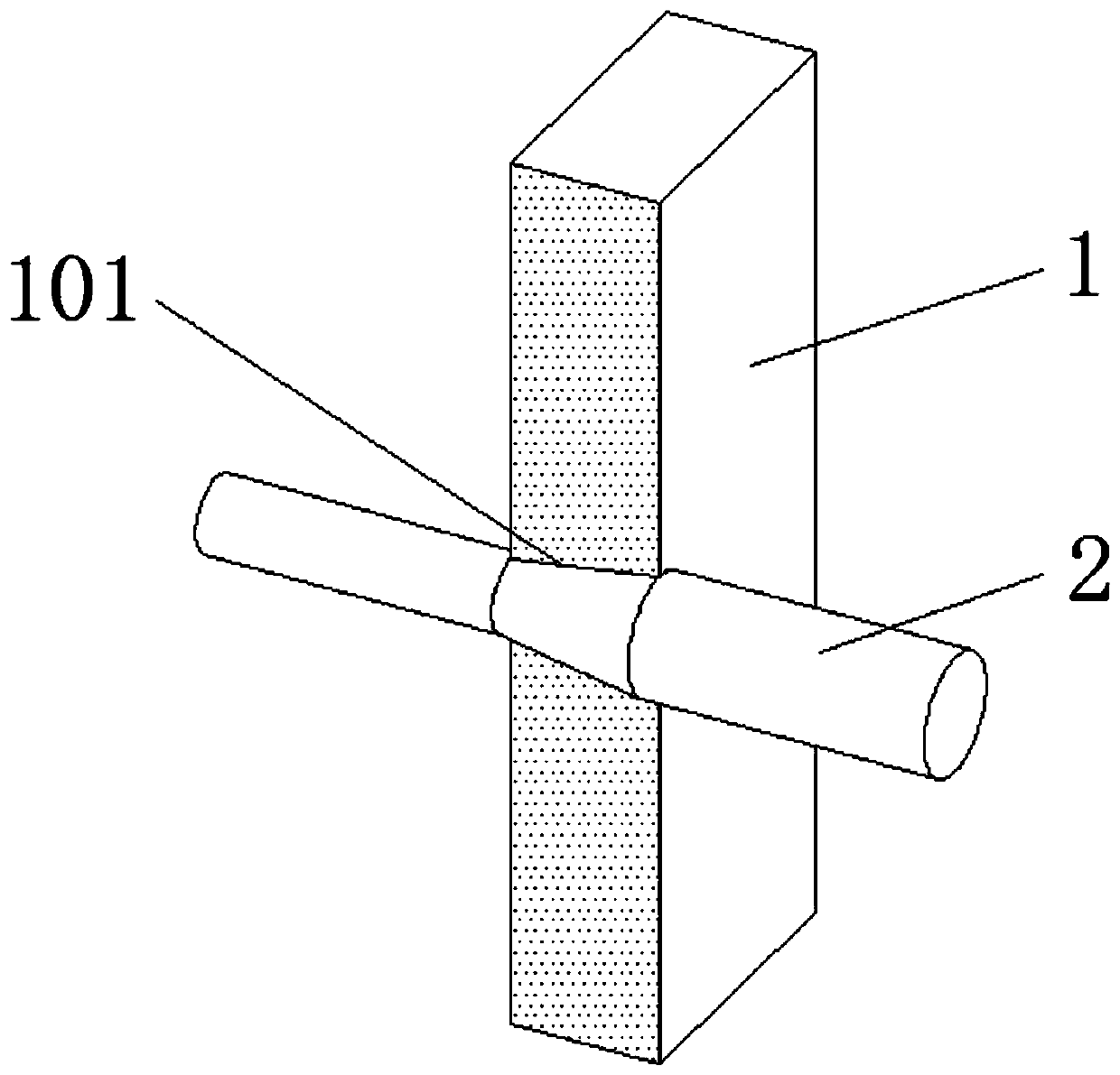
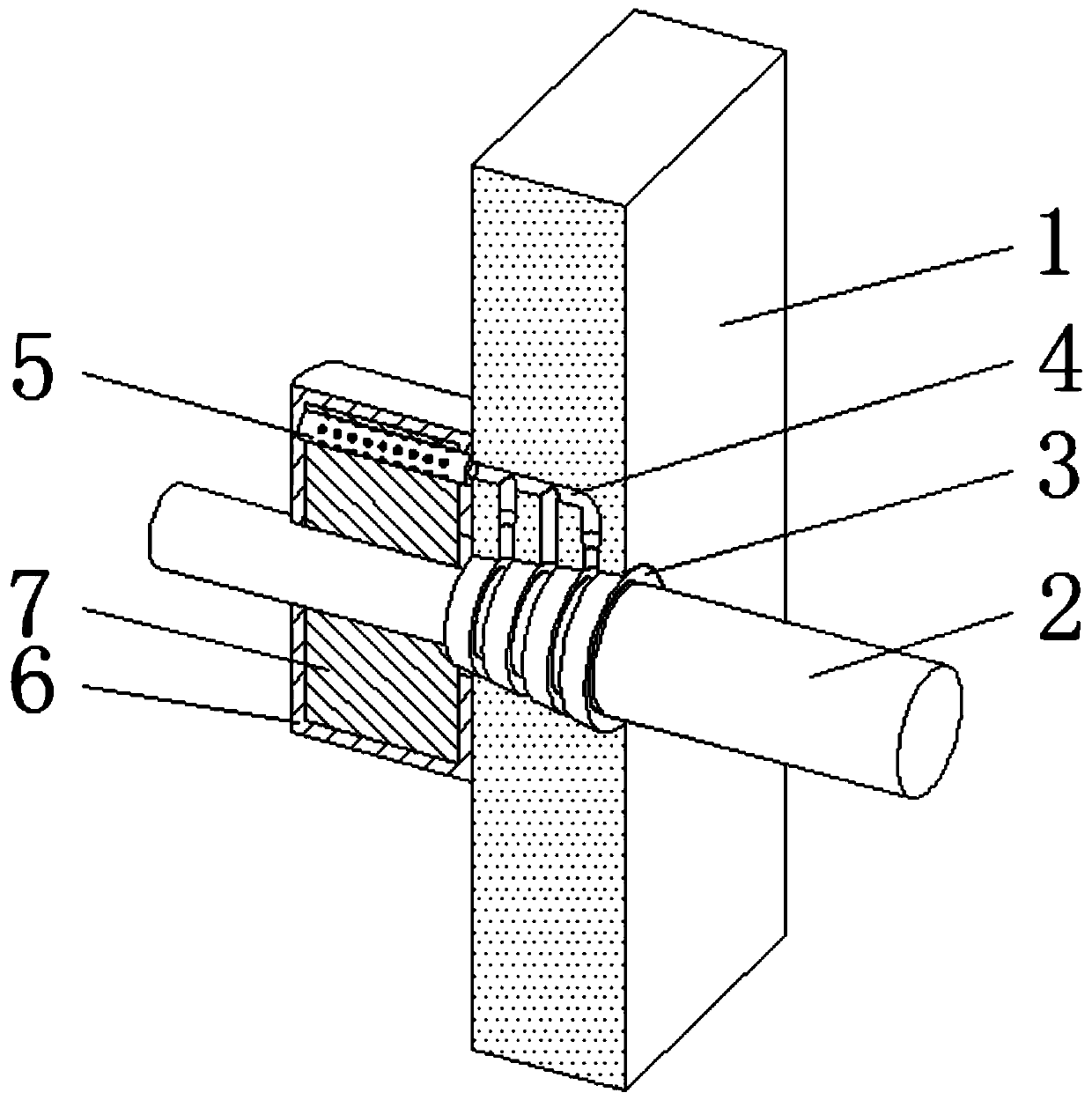
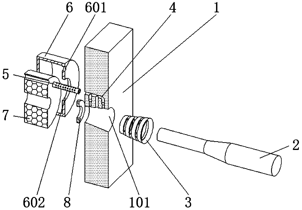
[0025] see Figure 2-5 , a combined wire drawing machine for preprocessing metal products, comprising a fixed die 1, a tapered hole 101 and a steel wire 2, the opening diameter of the right end of the tapered hole 101 is larger than the diameter of the steel wire 2, and is used for installing extrusion components, the tapered hole 101 Extrusion rings 3 are fixedly installed in the inner part of the body, the number of extrusion rings 3 is four, and the four ex...


PUM


Abstract

The invention relates to the technical field of combined wire drawing machines, and discloses a pre-processing combined wire drawing machine for a metal product. The combined wire drawing machine comprises a fixed die, a conical hole and a steel wire, the diameter of the opening of the right end of the conical hole is greater than that of steel wire, and an extrusion ring is fixedly arranged in the interior of the conical hole; a heat dissipation channel is formed in the position, located above the conical hole, of the interior of the fixed die, and a heat conduction pipe is fixedly arranged on the left side face of the fixed die and located on the outer side of the outlet of the heat dissipation channel; the left side face of the fixed die and the outer side of the outlet of the conical hole are fixedly provided with a heat preservation device. According to the pre-processing combined wire drawing machine for the metal product, when wire drawing is carried out on the wire drawing machine, the extrusion ring replaces the conical hole to extrude the steel wire, and the friction between the surface and the surface is converted into the friction between the surface and the wire, so that the friction heat is reduced, and the friction heat can be dissipated in time through the heat dissipation channel formed in the interior of the fixed die, so that the smoothness of the wire drawing process is ensured.

Description

technical field [0001] The invention relates to the technical field of combined wire drawing machines, in particular to a combined wire drawing machine for preprocessing metal products. Background technique [0002] Automatic wire drawing machine is a kind of mechanical equipment for cold drawing of metal wire or bar, so that the diameter, roundness, surface finish and other parameters of the raw material meet the production requirements. [0003] The wire drawing structure of the existing coupled wire drawing machine is divided into two types: fixed die and roller die. The structure of the fixed die is as follows: figure 1 As shown, by passing the steel wire through one end of the tapered hole opened on the stent, and pulling the steel wire out from the small end, the effects of reducing the cross-sectional area of ​​the steel wire and smoothing the surface can be achieved. Because the structure relies on the hard extrusion between the steel wire and the fixed die, a large...

Claims


Application Information

Patent Timeline
Patent Type & Authority Applications(China)
IPC IPC(8): B21C3/04B21C3/14
CPCB21C3/04B21C3/14
Inventor 不公告发明人
Owner 泰州市鑫中汇金属材料科技有限公司
Why Eureka
Eureka Blog
Learn More