
Continuous automatic cutting device of profile steel for building

An automatic cutting device, cutting device technology, applied in the direction of positioning device, feeding device, clamping, etc., can solve the problem of wasting time

Active Publication Date: 2019-09-17
湖北华信建设工程有限公司
View PDF6 Cites 4 Cited by
  • Summary
  • Abstract
  • Description
  • Claims
  • Application Information

AI Technical Summary

Problems solved by technology

[0005] The purpose of the present invention is to solve the above-mentioned problems, designing a continuous automatic cutting device for section steel for construction, which has the function of continuous automatic cutting, and solves the problem of wasting a lot of waste when the cutting blade contacts the section steel in the process of cutting section steel in the existing cutting device. The problem of cutting in a short time, by synchronously moving the cutting blade and the profile steel, so that the profile steel can be cut during the moving process, which can effectively save the time of profile steel cutting, thereby improving work efficiency

Method used


Image

  • Continuous automatic cutting device of profile steel for building
  • Continuous automatic cutting device of profile steel for building
  • Continuous automatic cutting device of profile steel for building

Examples


Embodiment Construction

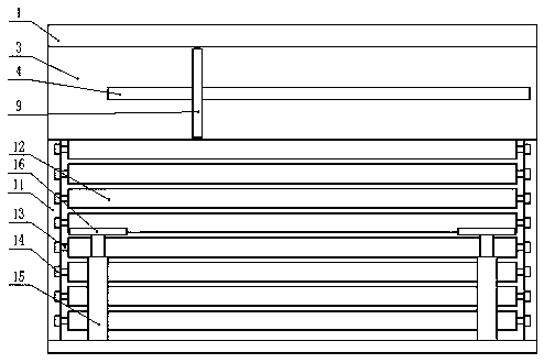
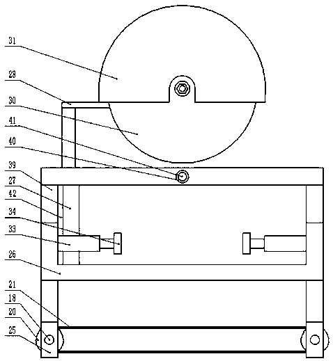
[0025] The present invention is specifically described below in conjunction with accompanying drawing, as Figure 1-4 As shown, in this implementation:

[0026] In this device, the device is powered by connecting with an external power supply, and the external power supply is connected to the controller 2, the frequency conversion speed regulating motor 5, the electric telescopic rod 15, the electromagnetic clutch 23, the hydraulic cylinder 27, the cutting motor 29 and the fixed electric telescopic rod 33. The type of controller 2 is PLC controller of FX1N-40MT-001 type. The control signal output end of controller 2 is respectively connected with frequency conversion speed regulating motor 5, electric telescopic rod 15, electromagnetic clutch 23, hydraulic The oil cylinder 27, the cutting motor 29 are electrically connected with the fixed electric telescopic rod 33, and the signal receiving end of the controller 2 is electrically connected with the signal sending end of the di...


PUM


Abstract

The invention discloses a continuous automatic cutting device of profile steel for building. The continuous automatic cutting device of the profile steel for building comprises a cutting base, wherein a profile steel storage device is arranged on one side of the cutting base, a controller is arranged on the cutting base, an automatic profile steel pushing device is arranged on one side above the cutting base, and a reciprocating cutting device is arranged on the other side of the cutting base. The T-shaped baffle plate is driven by a variable-frequency and variable-speed motor to move, so that the profile steel is pushed to move at a high speed; when a cutting position moves below a cutting blade, the rotating speed of the variable-frequency and variable-speed motor is adjusted, and a reciprocating screw starts to rotate under the action of an electromagnetic clutch, so that a U-shaped reciprocating platform can move synchronously along with the movement of the profile steel, and the cutting blade can cut the profile steel in the moving process, thus saving the cutting time.

Description

technical field [0001] The invention relates to the field of equipment related to section steel cutting for construction, in particular to a continuous automatic cutting device for section steel for construction. Background technique [0002] Section steel is a bar-shaped steel with a certain cross-sectional shape and size, and it is one of the four major types of steel. According to the section shape, section steel is divided into simple section section steel and complex section section steel. The former refers to square steel, round steel, flat steel, angle steel, hexagonal steel, etc.; the latter refers to I-beam, channel steel, rail, window frame steel, curved section steel, etc. [0003] In the patent CN201710705403.X-an automatic cutting and blanking equipment for H-shaped steel, the first motor is started to drive the H-shaped steel to roll on the roller frame. When the H-shaped steel slides to the right roller frame to squeeze the extrusion plate, by adding The mov...

Claims


Application Information

Patent Timeline
Patent Type & Authority Applications(China)
IPC IPC(8): B23D79/00B23Q3/06B23Q11/08B23Q7/06B23Q5/40
CPCB23D79/00B23Q3/062B23Q5/40B23Q7/06B23Q11/08Y02P70/10
Inventor 高国庆
Owner 湖北华信建设工程有限公司
Learn More