
Pneumatic clamp

A pneumatic clamp and air cylinder technology, applied in the field of machining, can solve the problems of unsuitable clamping of workpieces of different sizes, poor clamping stability, etc., and achieve the effect of convenient clamping, easy removal and reduction of parts.

Active Publication Date: 2019-09-17
JIANGSU UNIV OF TECH
View PDF8 Cites 3 Cited by
  • Summary
  • Abstract
  • Description
  • Claims
  • Application Information

AI Technical Summary

Problems solved by technology

[0004] In order to solve the problem that the clamps in the prior art cannot be applied to the clamping of various workpieces of different sizes, and the clamping stability is poor, the present invention proposes a pneumatic clamp to solve the above technical problems

Method used


Image

  • Pneumatic clamp
  • Pneumatic clamp
  • Pneumatic clamp

Examples


Embodiment Construction

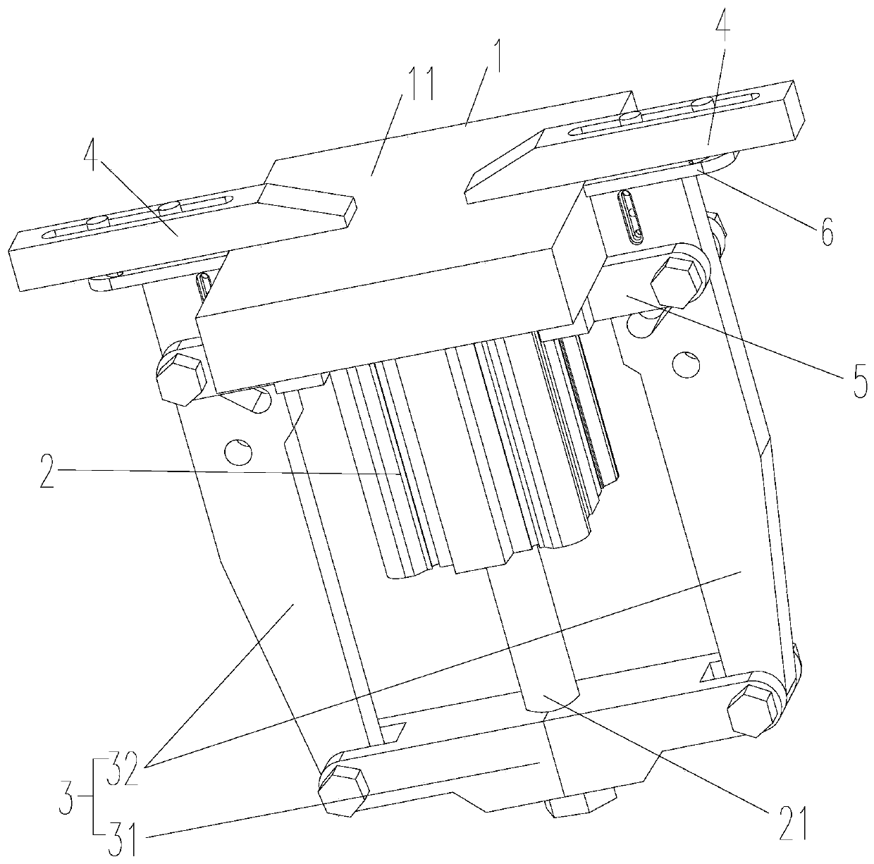
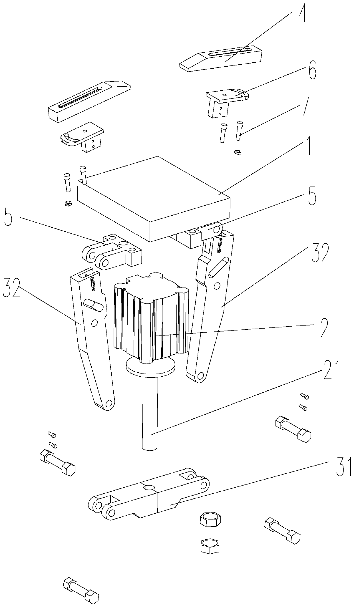
[0032] The content of the present invention will be further described below in conjunction with the accompanying drawings. In describing the present invention, it is to be understood that the terms "radial", "axial", "upper", "lower", "top", "bottom", "inner", "outer" etc. indicate orientation Or the positional relationship is based on the orientation or positional relationship shown in the drawings, which is only for the convenience of describing the present invention and simplifying the description, and does not indicate or imply that the referred device or element must have a specific orientation, be constructed and operated in a specific orientation , and therefore cannot be construed as a limitation of the present invention. In the description of the present invention, unless otherwise specified, "plurality" means two or more.

[0033] In the description of the present invention, it should be noted that unless otherwise specified and limited, the terms "installation", "s...


PUM


Abstract

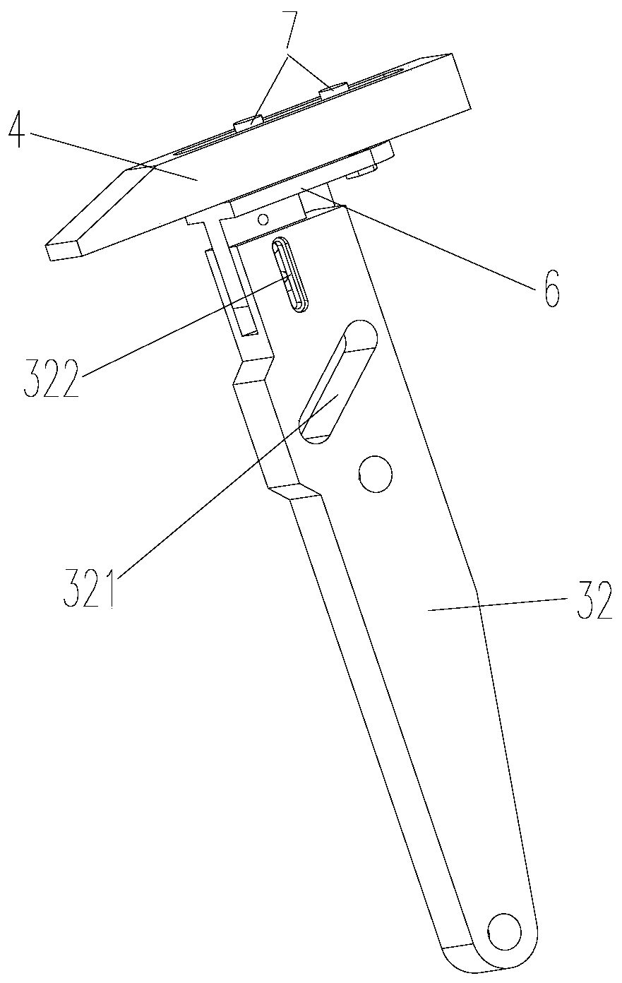
The invention relates to the technical field of machining, in particular to a pneumatic clamp. The pneumatic clamp comprises a workbench, an air cylinder, a connecting rod assembly and clamping parts, wherein the workbench is provided with a working face, the air cylinder is fixed on the side, far away from the working face, of the workbench, the telescopic end of the air cylinder stretches and retracts in the direction perpendicular to the working face, the two ends of the connecting rod assembly are located on the two opposite sides of the workbench correspondingly, the clamping parts are arranged at the two ends of the connecting rod assembly in a sliding mode, and the telescopic end of the air cylinder drives the clamping parts to do clamping action through the connecting rod assembly. The pneumatic clamp solves the problems that in the prior art, a clamp cannot be suitable for clamping workpieces of different sizes, and the clamping stability is poor.

Description

technical field [0001] The invention relates to the technical field of machining, in particular to a pneumatic clamp. Background technique [0002] The development of modern processing and manufacturing industry is changing with each passing day, from the original hand-made, to the later ordinary lathes, to the CNC lathes, machining centers, and now to the current process concentration, one person has multiple machines, and one machine has multiple parts. Machine tools are constantly developing, and fixtures are developed accordingly, from the original manual clamping to the current hydraulic clamping and pneumatic clamping. [0003] However, among the existing fixtures, pneumatic fixtures are widely used. For example, the application number CN201711217606.0 discloses a pneumatic clamp and milling machine, and specifically discloses: a pneumatic clamp includes a fixed plate, a fixed part and a moving part located above the fixed plate, wherein the fixed part and the moving ...

Claims


Application Information

Patent Timeline
IPC IPC(8): B23Q3/08
CPCB23Q3/08
Inventor 俞成涛苏雨桁邹于蓝
Owner JIANGSU UNIV OF TECH
Learn More